ICON USER’S MANUAL: SECTION 7 VIRGINIA PANEL CORPORATION
7-4 For the most current information available, visit www.vpc.com.
6/7/18
KEYING PIN KIT, RECEIVER AND ITA ASSEMBLY
PART # 310 113 461
TOOLS REQUIRED
Phillips Head Screwdriver
Flat Blade Screwdriver
ASSEMBLY INSTRUCTIONS
1. Align the keying pin in the desired location. Place
the keying pin in the hexagonal opening in the iCon
receiver. Figure A is a detailed view of the keying
feature.
2. Secure the keying pin with the 2-56 phillips head
screws (Figure B).
3. Remove the iCon ITA cover.
4. Place the other keying pin in the corresponding
location in the iCon ITA. Refer to Figure C.
5. Replace the iCon ITA cover.
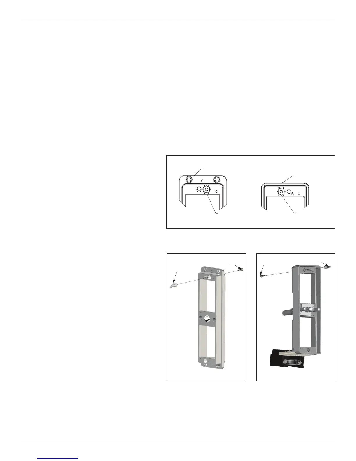
ICON ITA MATING FACE
KEYING NOMENCLATURE
KEYING NOMENCLATURE
ICON RECEIVER MATING FACE
Figure A. In order to mate the connector, the keying pin will be in the
same alphabetical positions in both the iCon receiver and ITA.
Figure B. The keying pin kit, Part #
310 113 461, includes two keying
pins and two screws.
Figure C. One keying pin kit will
allow 6 variations. By using a
second keying pin kit, you will
have 36 different variations.
The iSeries keying kit includes two pins and screws
which provide six different keying options. The
iCon system is designed to accept two kits which
increase the keying options to 36.
2-56 SCREW
KEYING
PIN
KEYING
PIN
2-56
SCREW
 Loading...