ICON USER’S MANUAL: SECTION 8 VIRGINIA PANEL CORPORATION
8-1 For the most current information available, visit www.vpc.com.
6/7/18
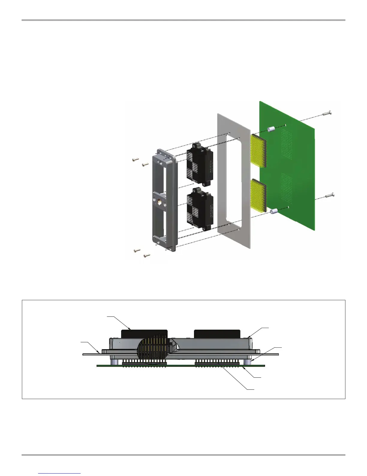
ICON PCB LAYOUT AND MOUNTING OVERVIEW
Figure A.
The iCon receiver is designed as a rack and panel
mount connector that can have a PCB attached
on the rear side. While it is capable of being
mounted directly to a PCB without an intermediary
panel, VPC recommends mounting the iCon
receiver to a panel and then mounting the PCB to
the other side of the panel using stand-offs (Figure
A). This will reduce the amount of stress the PCB
endures when the iCon is mated and un-mated.
Standard .100" spacing male header
Custom mounting panel
Threaded Stand off
iCon Receiver frame, 31012310
(customer desired length)
Custom printed circuit board
Receiver module with Quadrapaddle
Twin Female contacts, 510160105