ICON USER’S MANUAL: SECTION 8 VIRGINIA PANEL CORPORATION
8-2 For the most current information available, visit www.vpc.com.
6/7/18
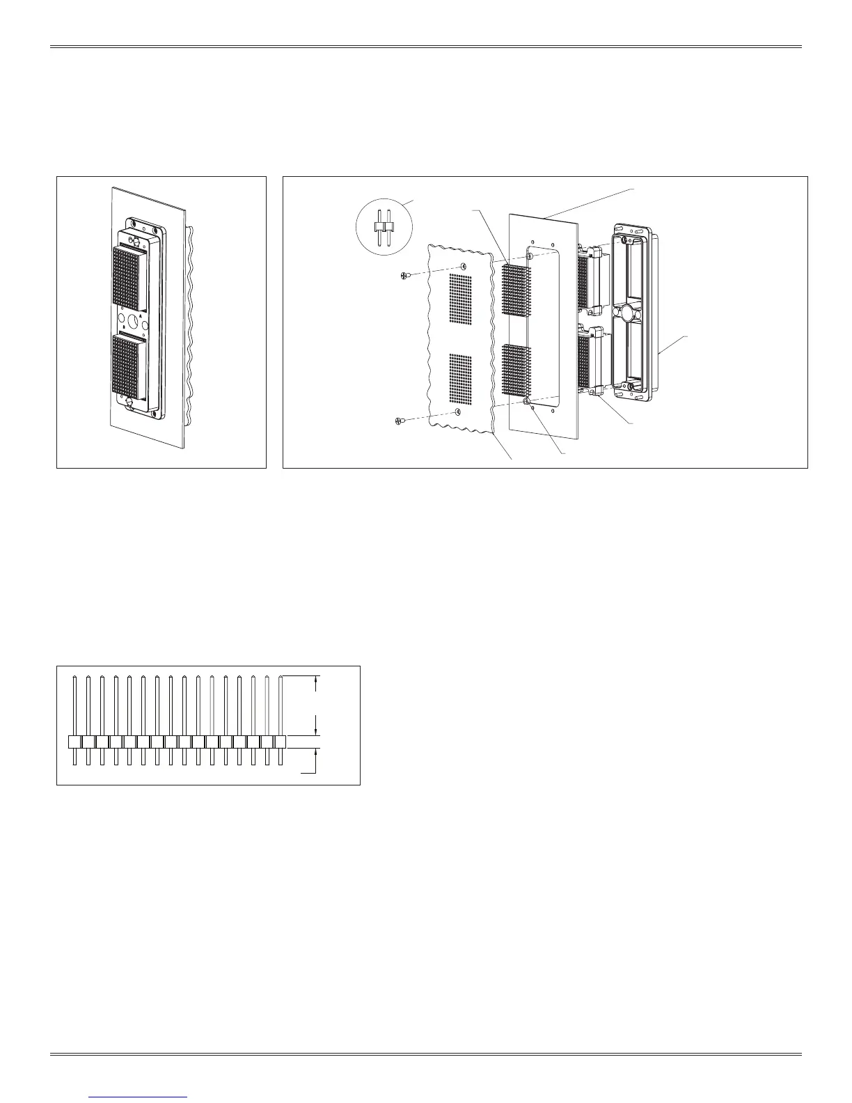
ICON PCB MOUNTING OVERVIEW
Figure B. iCon receiver with two
160 pin QuadraPaddle modules.
Each module is loaded with twin
female contacts, Part # 510 160 105.
Each module will accept twin male
headers connecting the female
contacts to the PCB plated thru holes.
Figure C. A PCB can be mounted directly to the back of an iCon receiver as shown above.
Use 2 x 4-40 screws (athead shown) to mount to the Receiver frame. When using twin male
headers, spacers may be needed to prevent unwanted stress on the PCB.
PCB - ENVELOP DIMENSIONS ARE NOT FIXED
TO PCB CREATES A
SEPARABLE INTERFACE
ICON RECEIVER FRAM
160 PIN TWIN FEMALE ICON MODULE
HEADER, .100 SPACING TWIN MALE SOLDERED
SPACER, SAME WIDTH AS HEADER BODY TO
RECEIVER FRAME MOUNTING PLATE
0.22” [5.6 mm]
/
0.45” [11.4 mm]
HEADER CARRIER HEIGHT
Figure D. Twin male header.
NOTE: Figure D details 0.22” [5.59 mm]/0.45” [11.43 mm] min/max
engagement.
NOTE: Minimum spacer height = 0.24” + header carrier height -
panel thickness (if used).
Any additional height beyond this minimum must be added to
the header post limits shown in Figure D.
NOTE: Several manufacturers offer the twin male header:
Samtec, TE, MultiComp, Molex. The specic part number
required is dependant on the distance the iCon will be located
from the PCB, the thickness of the PCB, and the plating type
required.
 Loading...