ICON USER’S MANUAL: SECTION 8 VIRGINIA PANEL CORPORATION
6/7/18
8-7 For the most current information available, visit www.vpc.com.
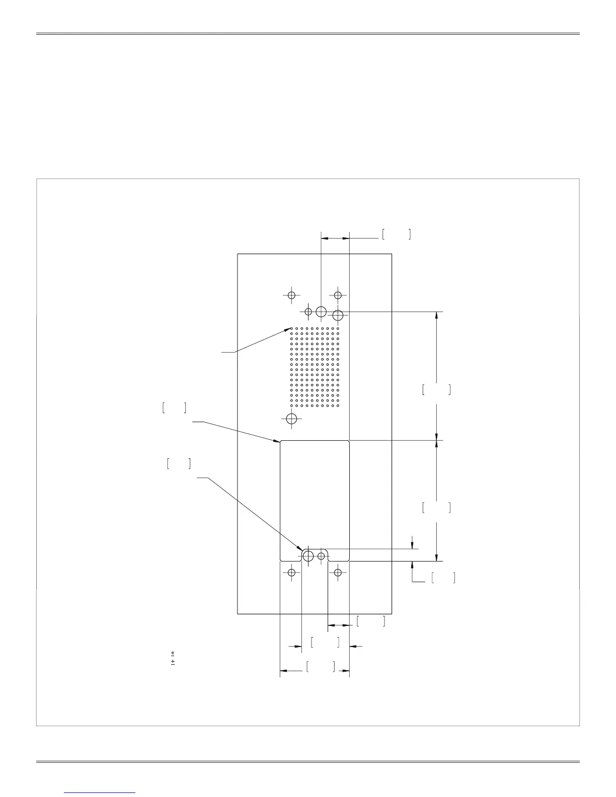
PCB layout for the iCon Receiver, Part # 310 123 101 loaded with one PCB mounted module
and one discretely wired module. Also shown are optional clearance holes. VPC modules/
pin mount this side. See Section 8-4 thru 8-6 for option hole pattern dimensioning.
PCB LAYOUT AND MOUNTING
ONE PCB MOUNTED MODULE AND ONE DISCRETELY WIRED MODULE
63.50
2.50
59.69
2.35
6.10
.24
10.92
.43
23.62
.93
34.29
1.35
2.54
R.10
2 PLCS.
1.27
R.05
2 PLCS.
13.97
.55
PIN A1
RECOMMENDED PCB LAYOUT
CONNECTOR MOUNTS THIS SIDE
TOLERANCES ARE:
.XX=
[0.25] .01
.XXX=
[0.13] .005
UNLESS OTHERWISE SPECIFIED
 Loading...