ICON USER’S MANUAL: SECTION 1 VIRGINIA PANEL CORPORATION
1-2 For the most current information available, visit www.vpc.com
6/7/18
iCON ITA PART IDENTIFICATION
PART # 410 123 XXX
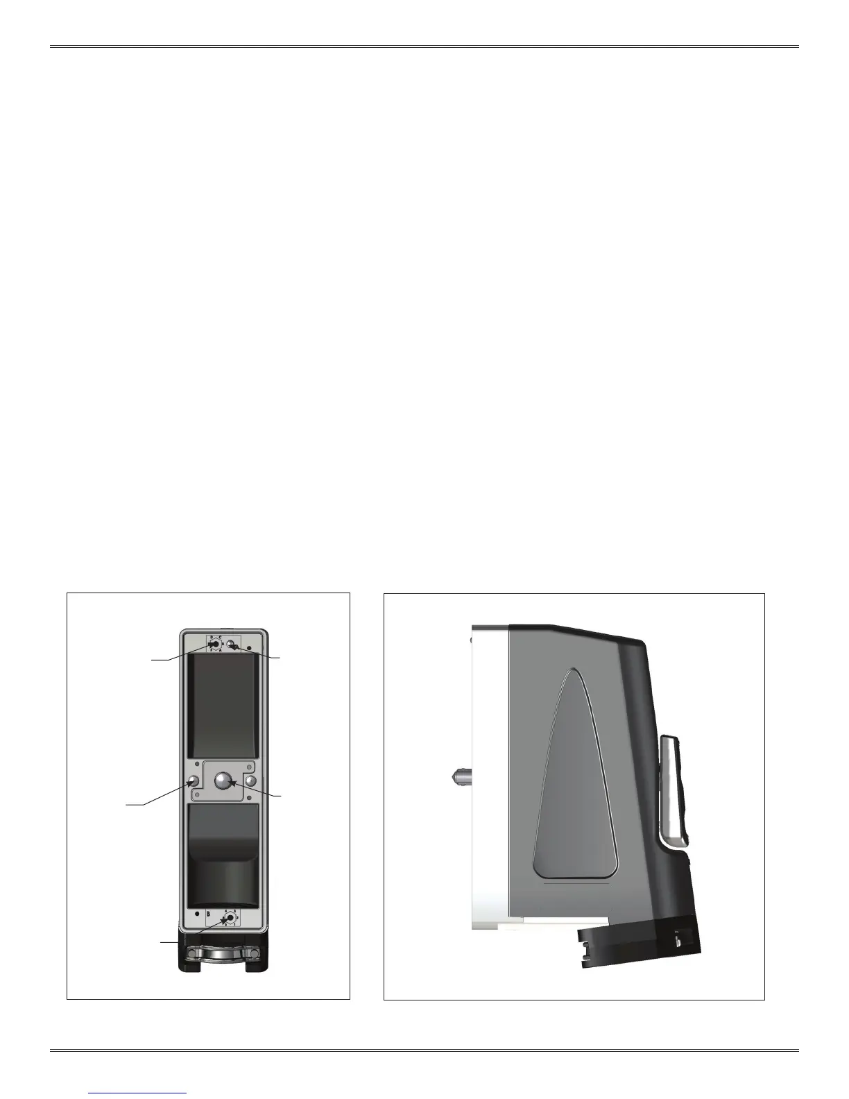
Figure A points out distinguishing features of the iCon ITA so that the top and bottom
can be identied. Features to look for are the alpha keying receptacle on the top
side and the numeric keying receptacle on the bottom. By holding the iCon ITA, the
top can be determined by holding it so the letters and numbers are readable.
The front and rear of the iCon ITA are easily distinguished as shown in Figure B. The
front has protruding guide pins, a locking mechanism, and the rear has the knob.
The front side mates with the iCon receiver. The front has a polarizing feature which
prevents the ITA and receiver from being engaged in the incorrect orientation. Wires
exit the iCon ITA through the 30° cable clamp exit.
Figure A. iCon ITA front view.
Figure B. iCon ITA side view.
Alpha Keying
Receptacle
Numeric Keying
Receptacle
Guide Pin
Locking
Mechanism
Top
Bottom
Front
Mating
Side
Rear
Wiring
Side
Polarizing
Feature
Cable Clamp with
30° Cable Exit
 Loading...