ICON USER’S MANUAL: SECTION 2 VIRGINIA PANEL CORPORATION
2-1 For the most current information available, visit www.vpc.com
6/7/18
ICON RECEIVER & ITA ENGAGEMENT & DISENGAGEMENT
RECEIVER • PART # 310 123 XXX, 310 124 XXX
ITA • PART # 410 123 XXX, 410 124 XXX
ENGAGEMENT INSTRUCTIONS
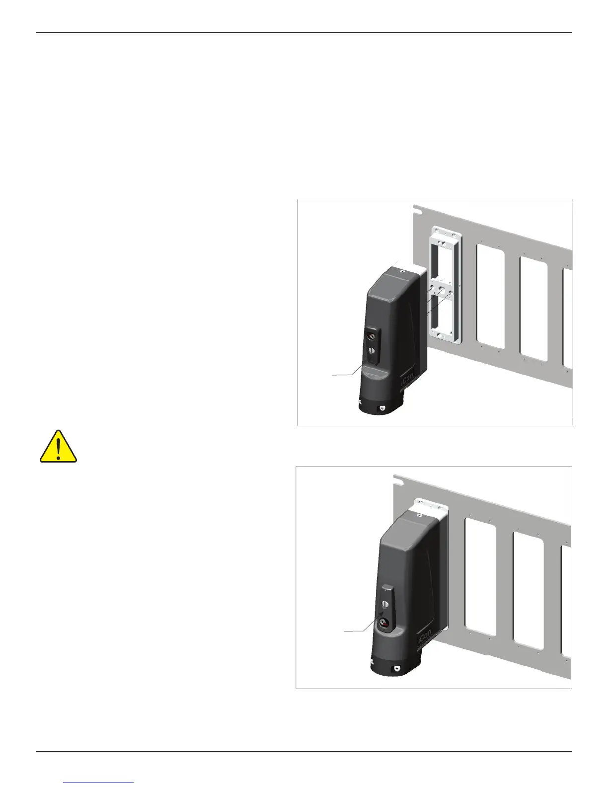
1. Turn the engagement handle to the open position as
shown in Figure A.
2. Align the dowel pins and push the ITA onto the
receiver. There will be about a 0.200″ gap.
NOTE: The iCon connector is polarized; the ITA will
not align if it is upside down.
3. Rotate the handle 180º clockwise (Figure B).
NOTE: For optimum performance and system longevity,
distribute the load evenly.
ENGAGEMENT INSTRUCTIONS
1. Turn the engagement handle to the open position.
2. Remove the ITA.
Figure A. When the engagement handle is open it will reveal the text
“OPEN” and the two raised circles will align.
Figure B. When the engagement handle is engaged, the raised
triangles will align.
MAXIMUM CONTACT MATING FORCE
SHOULD NOT EXCEED 100 LBS.
ENGAGEMENT
HANDLE
OPEN
ENGAGEMENT
HANDLE
CLOSED
 Loading...