ICON USER’S MANUAL: SECTION 4 VIRGINIA PANEL CORPORATION
4-1 For the most current information available, visit www.vpc.com.
6/7/18
TOOLS REQUIRED
Flat Head Screwdriver
Phillips Head Screwdriver
COVER REMOVAL INSTRUCTIONS
There are two options for removing the cover:
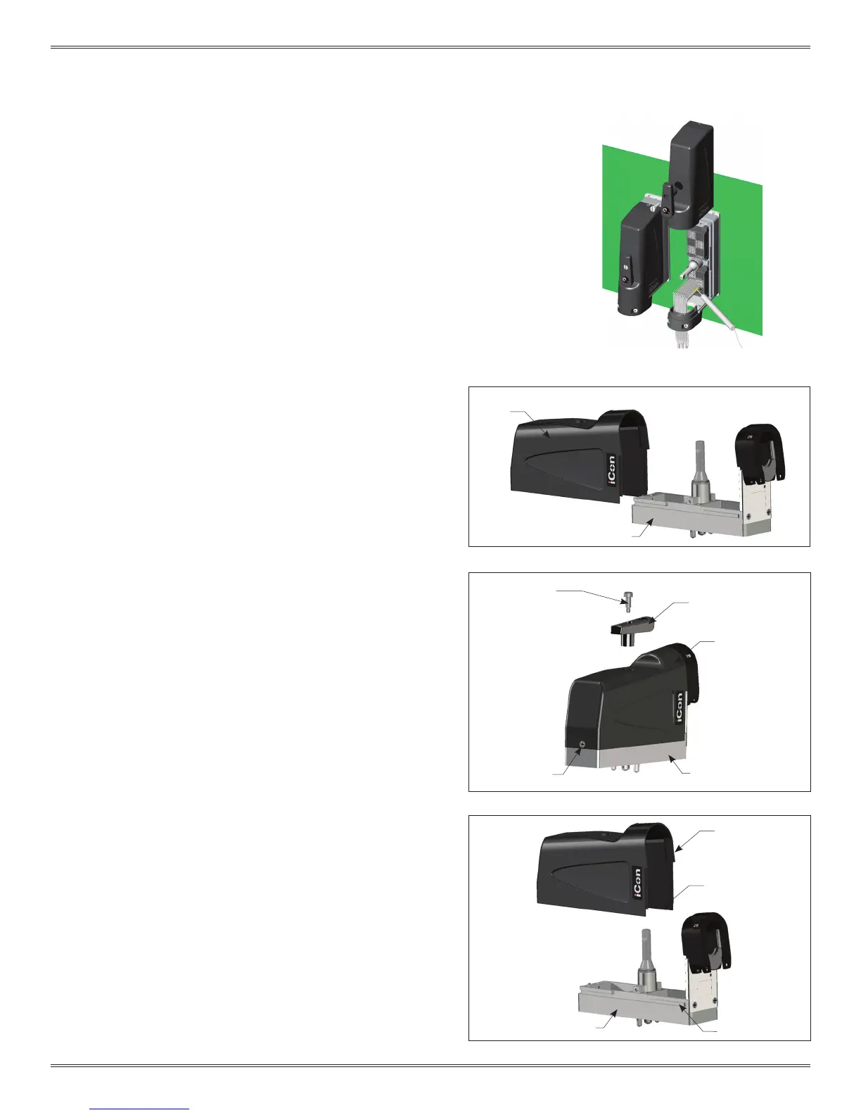
OPTION A: Slide the cover straight up the ITA frame (Figure A).
Option A requires 4.75″ of vertical space above the iCon.
OPTION B: Slide the cover halfway up the ITA frame then lift away
from the frame. This can be used if other components need to be
mounted above the iCon. Option B requires 1.64″ of vertical space
above the iCon.
OPTION A
1. Using a at head screwdriver remove the shoulder screw
located on the top of the removable cover (Figure B).
2. Remove the engagement handle by pulling it upward.
3. Loosen the captive screw with a Phillips head screwdriver
(Figure B).
4. Slide the cover off (Figure A).
OPTION B
1. Using a at head screwdriver remove the shoulder screw
located on the top of the removable cover (Figure B).
2. Remove engagement handle by pulling it upward.
3. Loosen the captive screw with a Phillips head screwdriver
(Figure B).
4. Slide the cover up until the cover notch within the cover aligns
with the notch on the ITA frame (Figure C).
5. With the notches aligned lift the cover up to remove it.
ICON ITA COVER REMOVAL
PART # 410 123 XXX
Figure B.
Figure A.
Figure C.
The iCon ITA is designed with a removable cover to allow
the test technician access to probe signal points while
troubleshooting the test set up.
REMOVABLE
COVER
SLOTTED SHOULDER
SCREW
REMOVABLE
COVER
REMOVABLE
COVER
ENGAGEMENT
HANDLE
COVER NOTCH
ITA FRAME
ITA FRAME
CAPTIVE
SCREW
NOTCH AREA
ITA FRAME
 Loading...