OSYSR225-EN
6/7
INSTALLATION, OPERATION & MAINTENANCE INSTRUCTIONS
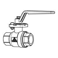
LEVER DIMENSIONS
Valve size [mm] Lever [mm]
Hex bolt
SR
SH
ST
SL
MS
MV
MH L H A
015
020
015
020
010
015
020
010
015
020
115 36 9
M5×15
025
032
025
032
025
032
025
032
145 46 11
040 -
040
050
040 220 52 14 M6×15
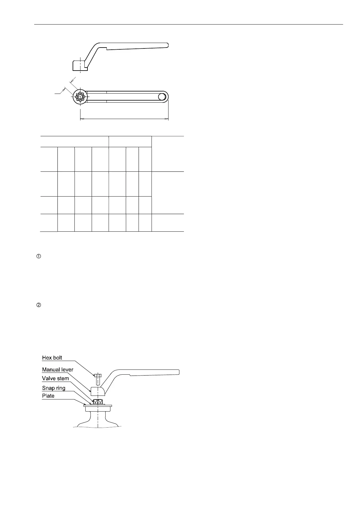
HANDLING OF MANUAL LEVER
Attention
• The lever handle is removed and shipped.
• The lever mounting direction can be changed in units
of 45 degrees.
• Do not apply excessive torque to the lever.
• Do not strike or extend the lever with a tool.
• The arrow on the plate indicates the direction of flow.
LEVER HANDLE INSTALLATION
• Plate of position indicator is attached on the valve by
C-type snap ring. Install the manual lever on it
tightening the bolt.
• The position of manual lever can be changed
according to piping circumstances.
L
A