VRG CONTROLS LLC. 12 of 60 JUNE 2021
VPC “BV” SERIES VALVE PILOT CONTROLLERS
INSTRUCTION MANUAL
VRG Controls LLC. 12 of 54 APRIL 21, 2019
NOTES
1. Adjustment and Installaon of VRG Controls equipment should be only
be performed by qualied personnel adequately trained and familiar with
products.
2. For technical assistance, please contact your local VRG Controls Sales
Representave or VRG Controls direct (www.vrgcontrols.com).
3. All values represent a starng point. Dynamic tuning with VPC in “live
control” will be necessary to opmize performance.
4. In this table, Pipeline Interconnects are dened >1.0 mile downstream
piping adjacent to control valve.
5. In this table, Close-Coupled System Applicaons are dened <1.0 mile
downstream piping adjacent to control valve.
6. Increasing number on the SUPPLY & EXHAUST ORIFICE will increase
the speed of response independently in each direcon (faster reset rate).
Refer to VPC Applicaon Schemac to determine which Adjustable Orice
controls OPEN and CLOSE speed.
7. Increasing number on the “D” TANK ORIFICE will introduces a DERIVATIVE
funcon controls the RATE of OUTPUT. Larger DERIVATIVE number of “D”
TANK Adjustable Orice introduces more dampening of the OUTPUT.
8. If stable control is achieved upon adjusng the VPC per the above
guidelines, the deadband may be reduced (smaller number on Sensivity
Adjusng Drum). For dynamic systems, do not reduce deadband to less
than “ZERO” as dened in Inial Adjustment Procedures.
9. If system is unstable upon adjusng VPC per above guidelines, correcve
adjustment to INCREASE CLOSING speed and REDUCE OPENING speed are
suggested. Addionally, the deadband may be increased (larger number on
Sensivity Adjusng Drum).
10. Top row - Worker // Boom Row - Monitor
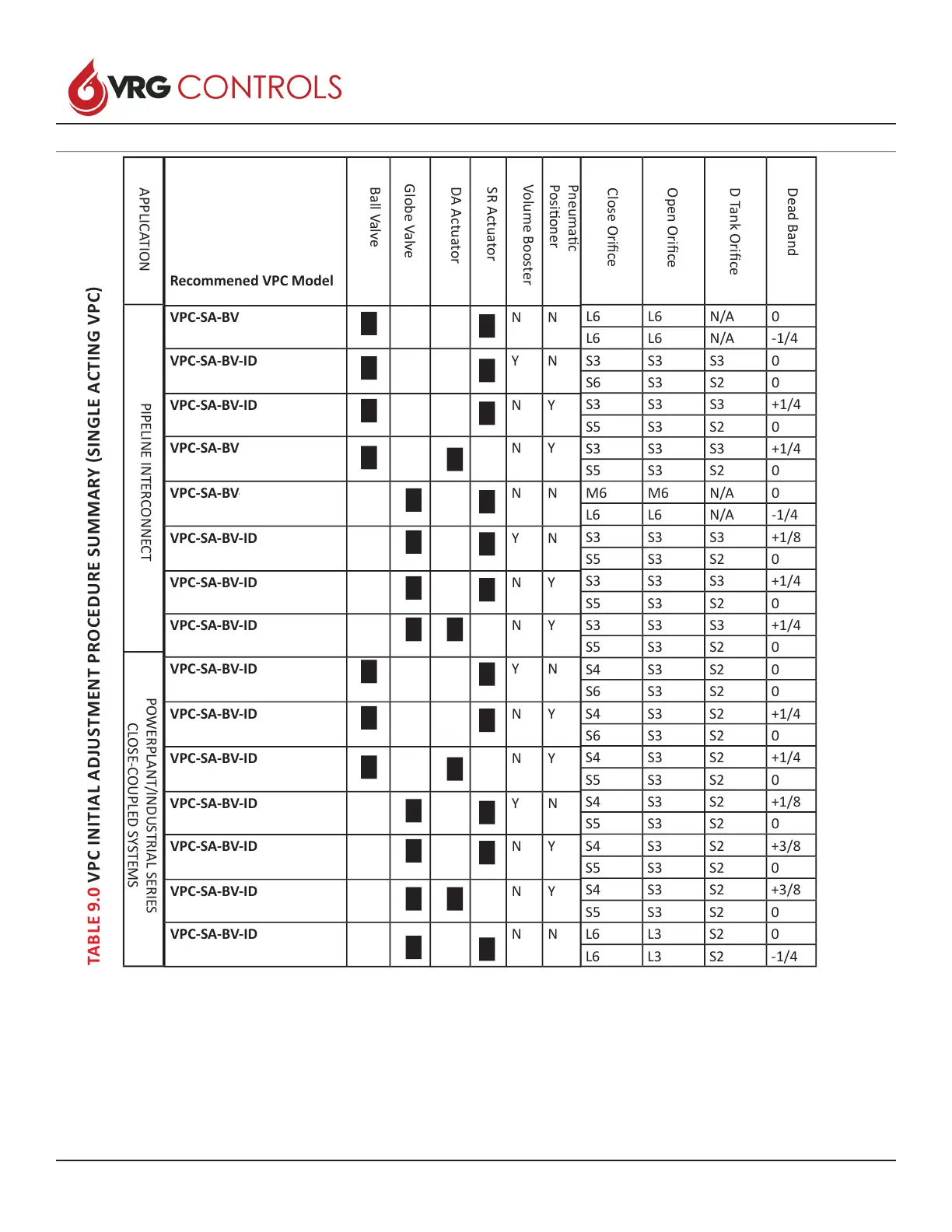
TABLE 9.0 VPC INITIAL ADJUSTMENT PROCEDURE SUMMARY (SINGLE ACTING VPC)
Recommened VPC Model
VPC-SA-BV N N
VPC-SA-BV-ID Y N
VPC-SA-BV-ID N Y
VPC-SA-BV N Y
VPC-SA-BV-ID N N
VPC-SA-BV-ID Y N
VPC-SA-BV-ID N Y
VPC-SA-BV-ID N Y
VPC-SA-BV-ID Y N
VPC-SA-BV-ID N Y
VPC-SA-BV-ID N Y
VPC-SA-BV-ID Y N
VPC-SA-BV-ID N Y
VPC-SA-BV-ID N Y
VPC-SA-BV-ID N N
L6 L6 N/A 0
L6 L6 N/A -1/4
S3 S3 S3 0
S6 S3 S2 0
S3 S3 S3 +1/4
S5 S3 S2 0
S3 S3 S3 +1/4
S5 S3 S2 0
M6 M6 N/A 0
L6 L6 N/A -1/4
S3 S3 S3 +1/8
S5 S3 S2 0
S3 S3 S3 +1/4
S5 S3 S2 0
S3 S3 S3 +1/4
S5 S3 S2 0
S4 S3 S2 0
S6 S3 S2 0
S4 S3 S2 +1/4
S6 S3 S2 0
S4 S3 S2 +1/4
S5 S3 S2 0
S4 S3 S2 +1/8
S5 S3 S2 0
S4 S3 S2 +3/8
S5 S3 S2 0
S4 S3 S2 +3/8
S5 S3 S2 0
L6 L3 S2 0
L6 L3 S2 -1/4
Ball Valve
Globe Valve
DA Actuator
SR Actuator
Volume Booster
Pneumac
Posioner
Close Orice
Open Orice
D Tank Orice
Dead Band
APPLICATION
PIPELINE INTERCONNECT
POWERPLANT/INDUSTRIAL SERIES
CLOSE-COUPLED SYSTEMS
 Loading...