4
1 1.1
(2)
(1)
(1)
2.1
2
(3)
(3)
(4)
(2)
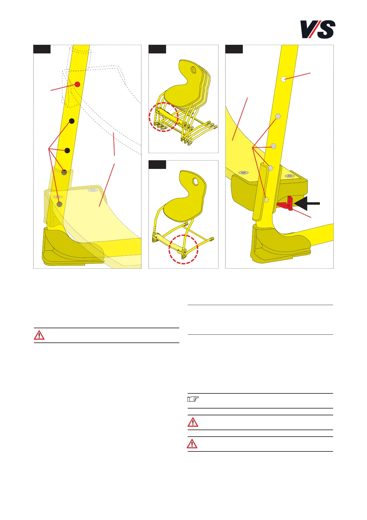
Height positions of the foot support
(Figure 1)
Chairs coded with a foot support (1) are supplied with the
foot support in the topmost hole (2).
The chairs can only be stacked if the foot support is in this
position (see Figure 1.1).
Caution! A maximum of 3 chairs may be stacked on
top of one another.
Before use, the foot support must be moved to a suitable
position for the user. Different height positions (3) are
possible depending on the model.
The relevant standard size as per DIN EN 1729-1 is indicated
in colour by the sticker on the adjustment unit or on the rear
of the chair back.
Model Standard size
31407 /31427 2-3
31408 /31428 4-5
31409 /31429 6
Adjusting the foot support (Figures 2
and 2.1)
Pull the levers (4) on the outside of the foot support for-
wards on both sides simultaneously to release the lock. You
can now slide the foot support to the required hole. Release
the levers to allow the lock to audibly engage.
Important! Do not tilt the foot support. The adjustment
operation should be as parallel as possible.
Caution! Each time the foot support is adjusted,
make sure that it has engaged again.
Caution! Before the chairs are stacked, the foot
support must be moved to the topmost position.