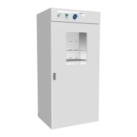
This document describes the VWR General Purpose Incubator models 1915A and 1925A, which are designed for professional, industrial, or educational use where the preparation or testing of materials is done at an ambient air pressure range of 22.14 – 31.3 inHg (75 – 106 kPa) and no flammable, volatile, or combustible materials are being heated. These units are suitable for use indoors, at room temperatures between 15°C and 30°C (59°F and 86°F), at no greater than 80% Relative Humidity (at 25°C / 77°F). Operating these units outside of these conditions may adversely affect its incubator temperature stability and effective operating range.
Function Description
The VWR General Purpose Incubator is designed to maintain a stable and controlled temperature environment for various applications. It utilizes a PID (Proportional – Integral – Derivative) control system to achieve and maintain the set temperature. When powered, the incubator heats to and maintains a user-selected target set point in the incubation chamber. A solid-state probe monitors the chamber interior wall, and if the incubator detects that the chamber temperature has dropped below the target set point, it pulses power to the heating element inside the chamber heating duct in the chamber ceiling. The incubator uses proportional control, meaning the rate of heating slows as the chamber temperature approaches the set point. The incubator uses minimum heating to control the rate of cooling and avoid dipping below the set point. The PID loops optimize heating rates for the temperature environment around the incubator, increasing the length of heating pulses to compensate if the incubator is operating in a cool room. In warm rooms, the incubator uses shorter pulses, and if ambient conditions change significantly, there may be minor over or undershoots as the incubator adapts. The incubators rely on natural heat radiation for cooling. These units can achieve a low-end temperature just above the ambient room temperature plus the internal waste heat of the unit. Air circulation within the incubation chamber is achieved by a heating duct located immediately above the chamber, which is designed to maintain chamber temperature uniformity and stability.
The incubator also features an Over Temperature Limit (OTL) system, which is a user-set, mechanical heating cutoff connected to a hydrostatic sensor probe inside the incubation chamber. This system operates independently of the main microprocessor temperature controller and routes power away from the incubator heating elements if the chamber temperature exceeds the OTL temperature cutoff setting. This helps safeguard the unit by preventing runaway heating in the event of electronic failures or a sudden external heat spike. The OTL must be set by the user in order to function, and a red indicator illuminates when the OTL is rerouting power.
Important Technical Specifications
Weight:
- 1915A: Shipping: 570 lb / 259 kg, Net: 406.0 lb / 184.0 kg
- 1925A: Shipping: 657 lb / 298 kg, Net: 497.0 lb / 225.0 kg
Dimensions (In Inches):
- 1915A: Exterior W × D × H: 38.8 x 34.3 x 76.9 in, Interior W × D × H: 32.5 x 26.0 x 63.3 in
- 1925A: Exterior W × D × H: 41.5 x 34.3 x 90.3 in, Interior W × D × H: 35.6 x 26.0 x 76.0 in
Dimensions (In Millimeters):
- 1915A: Exterior W × D × H: 985 × 871 × 1953 mm, Interior W × D × H: 825 × 660 × 1607 mm
- 1925A: Exterior W × D × H: 1054 × 872 × 2293 mm, Interior W × D × H: 904 × 660 × 1930 mm
Chamber Volume:
- 1915A: 30.9 Cubic Feet / 874.0 Liters
- 1925A: 38.6 Cubic Feet / 1093.0 Liters
Shelf Capacity:
- 1915A: Maximum Weight per Shelf: 75.0 lb / 34.0 kg, Max Total Weight: 450.0 lb / 204.0 kg
- 1925A: Maximum Weight per Shelf: 75.0 lb / 34.0 kg, Max Total Weight: 450.0 lb / 204.0 kg
- Note: Weight distributed evenly across the shelf. Exceeding this weight limit risks damaging the shelf standard rails and the chamber liner.
Temperature:
- 1915A: Range: Ambient +8° to 70°C, Uniformity: ±0.8°C @ 37°C, Stability: ±0.1°C
- 1925A: Range: Ambient +8° to 70°C, Uniformity: ±0.8°C @ 37°C, Stability: ±0.1°C
Power:
- 1915A: AC Voltage: 110 – 120, Amperage: 12.0
- 1925A: AC Voltage: 110 – 120, Amperage: 14.5
- Note: The unit must be positioned so that all end-users can quickly unplug the cord in the event of an emergency. Each unit comes provided with a 125 volt, 15 Amp, 9 ft 5 in (2.89 m) NEMA 5-15P power cord. Always use this cord or an identical replacement.
Required Clearances:
- 4 inches (102 mm) of clearance is required on the sides and back.
- 2 inches (51 mm) of headspace clearance is required between the top of the unit and any overhead partitions.
- Door Swing: 1915A: 36.0" (914 mm), 1925A: 42.3" (1075 mm).
Usage Features
Installation:
- Pre-Installation Checklist: Verify ambient conditions, spacing clearance, unit dimensions, and power supply.
- Location: Install the incubator in a suitable workspace location, reviewing lifting and handling instructions, leveling the unit, and ensuring it is in its workspace location.
- Setup: Clean and disinfect the unit and shelving (recommended), install shelving, and verify the port cap has been installed in the access port.
- Lifting and Handling: The unit is heavy; use appropriate lifting devices. Lift the unit only from its bottom surface. Doors, handles, and knobs are not adequate for lifting or stabilization. Restrain the unit completely while lifting or transporting. Remove all moving parts, such as shelves and trays, and lock doors in the closed position during transfers to prevent shifting and damage.
- Leveling: Install the 4 leveling feet in the 4 corner holes on the bottom of the unit. The unit must be level and stable for safe operation. To prevent damage when moving the unit, turn all 4 leveling feet so that the leg of each foot sits inside the unit.
- Deionized and Distilled Water: Do not use deionized water to clean the unit, even if DI water is readily available in your laboratory, as deionized water may corrode metal surfaces and voids the manufacturing warranty. The manufacturer recommends the use of distilled water in the resistance range of 50K Ohm/cm to 1M Ohm/cm, or a conductivity range of 20.0 uS/cm to 1.0 uS/cm, for cleaning applications.
- Shelving Installation: Install 4 shelf clips in the slots of the shelf standard mounting rails on the sides of the chamber interior. Squeeze each clip, insert the top tab first, and then the bottom tab using a rocking motion. Set the shelf on the clips and verify it is level.
- Access Port: Always leave the access port cap in place, except when introducing sensor probes into the chamber. Removing the cap during normal operations can adversely impact temperature stability and uniformity.
Operation:
- Power On: Plug in the power cord to the inlet receptacle on the left side of the incubator and then to the workspace electrical outlet. Turn on the incubator by pressing the power switch.
- Set Temperature: Use the Up and Down arrow buttons to adjust the Set Point (SP) or Calibration Offset (CO) display modes and input the temperature set point or calibration adjustment value. The heating indicator light illuminates when the incubator powers the chamber heating elements.
- Heat Soak: Allow the incubator to heat soak for a minimum of 8 hours (for example, overnight) with the chamber door closed prior to loading samples. This includes setting the Over Temperature Limit.
- Set Over Temperature Limit (OTL): This procedure sets the mechanical heating cutoff to approximately 1°C above the current chamber temperature. Perform this procedure when the unit has been running with no temperature fluctuations at your application temperature for at least 8 hours. Turn the dial counterclockwise until the Over Temperature Activated light illuminates, then slowly turn the dial clockwise until the light turns off. Leave the OTL dial set just above the activation point.
- Loading Samples: The manufacturer strongly recommends waiting at least 8 hours after putting the incubator in operation before loading samples in the chamber. Proper spacing allows for maximum air circulation and a higher degree of temperature uniformity. Proper spacing also decreases the chance of condensate forming in the incubator when operating with a large number of samples in the chamber.
- Chamber Accessory Power Outlets: The incubator is provided with four 110 – 120-volt, 1-amp power outlets inside the chamber. Do not attach powered equipment that draws more than 1 amp. Verify that any powered accessory equipment used inside the chamber can safely and effectively operate within your selected temperature range. Powered equipment, such as stirrers or shakers, can generate heat sufficient to disrupt the thermal uniformity and stability of the chamber.
- Humidifying the Incubator: Long-term use of a large water container, such as a humidifier pan, will create excess water vapor in the unit and can damage the electrical components of the incubator. Additionally, the use of deionized water may cause significant corrosion damage to the incubator. Overloading the unit with sample media may also damage the incubator from excessive media evaporation and disruption of airflow pathways through the shelf space. For small sample loads, placing a small number of Petri dishes or other media containers in the incubator chamber may lead to excessively fast drying of sample media. A small water-filled container, such as an open flask, may be placed in the chamber to help slow sample drying with small loads.
- Condensation and the Dew Point: Relative humidity inside the incubation chamber should never be allowed to exceed 80% at 25°C. Exceeding this threshold will likely result in condensation or possible leaks around the incubator, and may cause corrosion damage if allowed to continue for any significant length of time. Condensation takes place whenever the humidity level in the incubation chamber reaches the dew point. The dew point is the level of humidity at which the air cannot hold more water vapor. The warmer the air, the more water vapor it can hold. As the level of humidity rises in an incubation chamber, condensate will first appear on surfaces that are cooler than the air temperature. Near the dew point, condensate forms on any item or exposed surface even slightly cooler than the air. When the dew point is reached, condensate forms on nearly all exposed surfaces. Managing condensation primarily depends on either lowering the humidity level or increasing the air temperature in the incubation chamber. Ensure samples on the shelves are evenly spaced to allow for good airflow. Ensure the chamber door is closing and latching properly. Verify the chamber access port is closed. The black, plastic shipping cap that came with the unit should be installed on the outside of the incubator and not in the chamber. Are frequent or lengthy chamber door openings causing significant temperature disruptions and chilling the chamber surfaces? If so, reduce the number of openings. Are there too many open or “breathable” containers of evaporating sample media in the chamber? If so, reduce the number of open sample containers. Does the ambient humidity in the room exceed the stated operating range of 80% relative environmental humidity? If so, lower the room humidity. Is the incubator exposed to an external flow of cold air such as an air-conditioning vent or a door to a cooler hallway or adjacent room? Block or divert the air, or reposition the unit. Check the door gasket for damage, wear, or signs of brittleness or dryness. Arrange for replacement of the gasket if damaged or excessively worn.
Maintenance Features
Cleaning and Disinfecting:
- Disconnect the unit from its power supply.
- Remove all removable interior components such as shelving and accessories.
- Clean the unit with a mild soap and water solution, including all corners.
- Do not use an abrasive cleaner. These will damage metal surfaces.
- Do not use deionized water to rinse or clean with.
- Take special care when cleaning around the temperature sensor probes in the chamber to prevent damage. Do not clean the probes.
- Rinse with distilled water and wipe dry with a soft cloth.
- Disinfecting: Always turn off and disconnect the unit to safeguard against electrical hazards. For maximum effectiveness, disinfection procedures are typically performed after cleaning. Disinfect the unit chamber using commercially available disinfectants that are non-corrosive, non-abrasive, and suitable for use on stainless steel and glass surfaces. Contact your local Site Safety Officer for detailed information on which disinfectants are compatible with your applications. If permitted by your protocol, remove all removable interior accessories (shelving and other non-attached items) from the chamber. Disinfect all surfaces in the chamber, making sure to thoroughly disinfect the corners. Exercise care to avoid damaging the sensor probes. Gas concentrations from evaporating disinfecting agents can inhibit growth or cause metabolic symptoms in microbiological sample populations. Make sure that chlorines, quaternary ammonias, or any other overly volatile disinfecting agents have been rinsed or otherwise removed from the surfaces, prior to placing samples in the chamber. When disinfecting external surfaces, use disinfectants that will not damage painted metal, glass, and plastic.
Minimizing Contamination Exposure:
- Maintain a high air quality in the laboratory workspaces around the incubator.
- Avoid placing the incubator near sources of air movement such as doors, air vents, or high traffic routes in the workspace.
- Minimize the number of times the incubator chamber door is opened during normal operations.
Door Components:
- Periodically inspect the door latch, trim, catch, and gasket for signs of deterioration. Failure to maintain the integrity of the door system shortens the life span of the unit.
Electrical Components:
- Electrical components do not require maintenance. If the incubator fails to operate as specified, please contact your distributor or Technical Support for assistance.
Storing the Incubator:
- Perform the following steps if the incubator will be out of use for more than 24 hours to prevent microbiological contamination such as fungus or mold.
- Depower the incubator.
- Disinfect and clean if required by your laboratory protocol, or if the chamber has been exposed to pathogenic microorganisms.
- Use a soft cloth to dry the chamber surfaces.
Calibrate the Temperature Display:
- Performing a temperature display calibration requires a temperature reference device. Please see the Reference Sensor Device entry on page 7 for the device requirements.
- Temperature calibrations are performed to match an incubator temperature display to the actual air temperature inside the incubation chamber. The actual air temperature is supplied by a calibrated reference device. Calibrations compensate for long-term drifts in the incubator microprocessor controller as well as those caused by the natural material evolution of the sensor probe in the heated incubator space. Calibrate as often as required by your laboratory or production protocol, or regulatory compliance schedule. Always calibrate to the standards and use the calibration setup required by your industry requirements or laboratory protocol.
- The incubator must run for at least 8 hours prior to conducting a calibration.
- The temperature is considered stabilized when the incubator has operated with the door closed at your calibration temperature for at least 1 hour with no fluctuations greater than the specified stability of the unit (see page 40).
- Calibration Procedure:
- Once the unit temperature has stabilized, compare the reference device and incubator temperature display readings. If the readings are the same, or the difference between the two falls within the acceptable range of your protocol, the display is accurate, showing the temperature in the chamber. The Temperature Calibration procedure is now complete. If the difference falls outside of your protocol range, advance to step 2.
- A display calibration adjustment must be entered to match the display to the reference device. Use the Up and Down arrow buttons simultaneously for approximately 5 seconds. Release the buttons when the temperature display shows the letters “C O”. The display will begin flashing the current temperature display value.
- Use the Up and Down arrow buttons to adjust the current display temperature value until it matches the reference device temperature reading.
- After matching the display to the reference device, wait 5 seconds. The temperature display will cease flashing and store the corrected chamber display value. The incubator will now begin heating or passively cooling in order to reach the set point with the corrected display value.
- Allow the incubator to operate for at least 1 hour undisturbed to stabilize after the incubator has achieved the corrected temperature set point. Failure to wait until the incubator is fully stabilized will result in an inaccurate reading.
- Compare the reference device reading with the chamber temperature display. If the reference device and the chamber temperature display readings are the same or the difference falls within the range of your protocol, the incubator is now calibrated for temperature. If the difference still falls outside the acceptable range of your protocol, repeat steps 3 – 7 up to two more times.
- If the temperature readings of the incubator temperature display and the reference device still fall outside your protocol after 3 calibration attempts, contact your distributor or technical support for assistance.