Do you have a question about the VWR 2005 and is the answer not in the manual?
Inspect for visible exterior damage, note on freight bill, and enter claim with carrier.
Inspect unit interior and exterior for concealed loss or damage; arrange carrier inspection if needed.
Save crate, contact representative for authorization, provide nameplate data including model/serial numbers.
Check packing slip for all included equipment, carefully check packaging before discarding.
Ensure electrical supply conforms to codes, check serial plate for voltage/cycle/wattage/ampere requirements.
Choose a location with stable temperatures, avoid direct sun, drafts, and ensure 20cm clearance for airflow.
Use rated lifting devices, lift from bottom, restrain unit, remove moving parts, lock doors during transport.
Ensure unit sits level and solidly by adjusting leveling feet counterclockwise to raise.
Clean with appropriate disinfectant; avoid abrasives and spray cleaners that may damage interior or electrical parts.
Controls all power to the unit; must be ON for systems to operate.
Marked "SET TEMPERATURE"; uses digital display and arrow pads for setting and calibration.
Marked "TEMPERATURE ACTIVATED"; ON when heating, blinking when at set point.
Independent override control, acts if main controller fails ON.
Marked "OVERTEMPERATURE ACTIVATED"; ON when thermostat is activated.
Added protection against power variations; reset by pushing button after clearing interruption.
Added protection against power variations; must be replaced if blown to power up unit.
Verify power supply matches unit serial plate before plugging in service cord.
Plug in cord, turn power switch to I/On, set Overtemperature Thermostat to max.
Use Up/Down arrow pads to enter desired set point temperature; allow unit 24 hours to stabilize.
Compare chamber temp to reference thermometer, enter calibration mode if difference is unacceptable.
Set thermostat counterclockwise until light turns on, then clockwise until it turns off and slightly beyond.
Internal 1 amp outlet powers accessories; ensure apparatus draws 1 amp or less.
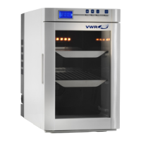
Load chamber with sample bottles stacked upright, not flat, for optimal capacity and uniformity.
Disconnect power, remove parts, clean with soap/water, use appropriate disinfectant; avoid chemicals.
Vacuum compressor compartment every six months to ensure proper airflow and maximum efficiency.
If ice builds up, eliminate causes (open containers, door openings), turn unit OFF, open door, remove items.
Remove all items, ensure chamber is dry, screw in leveling feet, review lifting/handling for transport.
Addresses problems with temperature too high/low, display errors, and heating unit failure.
Troubleshoots unstable readings and discrepancies between displayed and reference thermometers.
Diagnoses issues when the unit fails to cool, checking compressor and fan operation.
Resolves ice accumulation in the chamber and diagnoses operational noises like clicking or fan issues.
Addresses motor problems (rubbing, binding, noise) and ensures proper door gasket sealing.
Troubleshoots blown fuses/breakers, unit not turning on, and checks wall circuit loads.
Refers to cleaning procedures and SOPs for applications to prevent contamination.
| Brand | VWR |
|---|---|
| Model | 2005 |
| Category | Accessories |
| Language | English |