EasyManua.ls Logo

W.E.S.T. Elektronik POS-123-U-SSI - User Manual

Default Icon
57 pages
Print Icon
To Next Page IconTo Next Page
Loading...
Technical Documentation
POS-123-U
POS-123-P
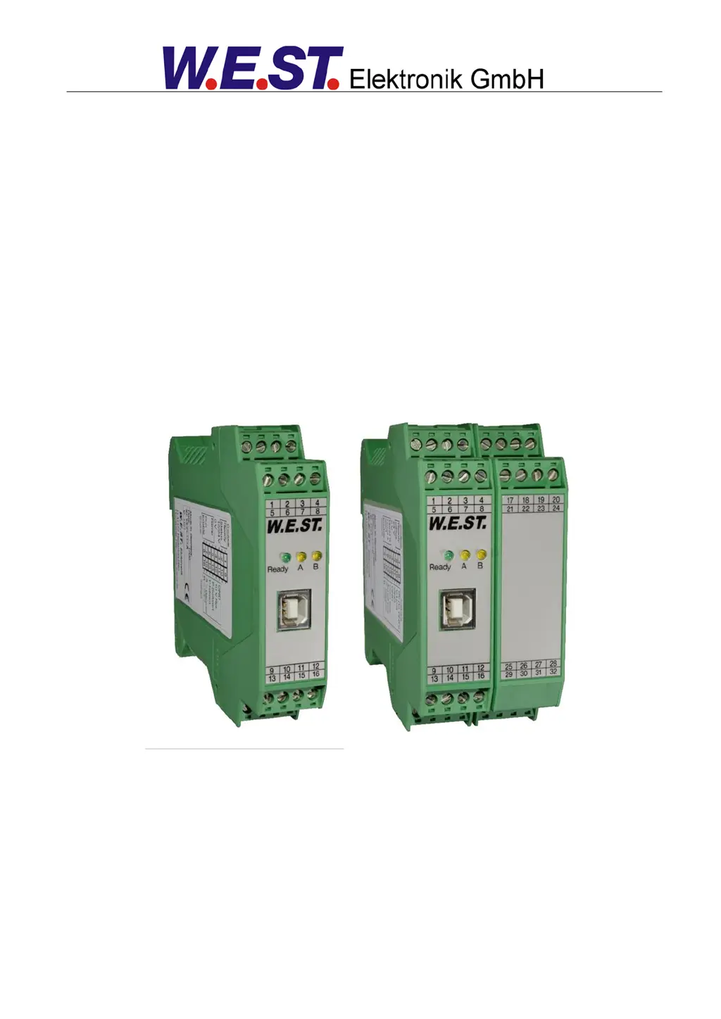
POS-123-U-SSI
Universal positioning module, alternatively with power output stage or SSI interface

Table of Contents

Questions and Answers

  • S
    Stephanie SingletonAug 7, 2025
    What to do if W.E.S.T. Elektronik POS-123-U-SSI Control Systems have positioning error?
    • C
      Cindy YoungAug 7, 2025
      Serious positioning errors with W.E.S.T. Elektronik Control Systems can stem from incorrect parameterization or system design. Verify the cylinder position is correctly specified. Ensure deceleration strokes are correct, ideally around 20-25% of the cylinder position for system startup. Determine if the valve is a zero lapped control valve or a standard proportional valve; for proportional valves, compensate for any valve overlap using the MIN parameters, referring to the valve data sheet for typical values.
  • C
    christophersloanAug 12, 2025
    Why W.E.S.T. Elektronik Control Systems oscillate on the target?
    • K
      Kathleen MorrisonAug 12, 2025
      If your W.E.S.T. Elektronik Control System oscillates on the target, it could be due to the parameterization not being adjusted to the system (gain too high). To resolve this, reduce the gain by increasing deceleration distances for D:A and D:B. If you have overlapped valves, reduce the MIN parameter as well.
  • J
    Jerry RodriguezAug 17, 2025
    What to do if speed is too high in W.E.S.T. Elektronik POS-123-U-SSI?
    • J
      John MillerAug 17, 2025
      If the drive in your W.E.S.T. Elektronik Control System moves too fast, resulting in uncontrolled behavior, it could be due to an over-sized hydraulic system. In this case, the parameterization of the movement cycle (overlap and deceleration distance settings) cannot be reproduced. Reducing the speed (MAX or VELO parameter) will likely have little to no effect.
  • H
    Heather HardyAug 22, 2025
    Why is READY LED flashing in W.E.S.T. Elektronik Control Systems?
    • K
      Katherine OwensAug 22, 2025
      If the READY LED is flashing on your W.E.S.T. Elektronik Control System, it indicates a detected fault. This could be due to a broken cable or no signal at the input (PIN 13 or PIN 14) if 4…20 mA signals are parameterized, a broken cable or incorrect cabling to the solenoids (in the P version only), an issue with the SSI sensor, or an internal data error. To resolve a data error, press the command/SAVE button to reload the DEFAULT data. You can localize the fault directly via the monitor using the WPC-300 operating program.
  • K
    Katrina PetersonAug 27, 2025
    How to troubleshoot low speed in W.E.S.T. Elektronik Control Systems?
    • R
      rogerreeseAug 27, 2025
      If the drive in your W.E.S.T. Elektronik Control System moves to position too slowly, check the control signal to the valve using the integrated oscilloscope (U variable) or an external oscilloscope/voltmeter. If the control is within ± 100 % (± 10 V), the issue is likely in the hydraulics. If the control signal is low, check if the internal/external speed signal is limiting the speed and verify the deceleration distance setting relative to the POSITION.
  • R
    Rita LewisSep 1, 2025
    What to do if W.E.S.T. Elektronik Control Systems move to end position?
    • S
      Sharon Goodman DDSSep 1, 2025
      If your W.E.S.T. Elektronik Control System moves to an end position when ENABLE is active, it indicates that the control circuit polarity is incorrect. You can correct this by using the POL command or by reversing the connections to PIN 15 and PIN 16.

Summary

General Information

Safety Instructions

Details critical safety precautions, warnings, and guidelines for safe device operation.

Use and Application

Installation Instructions

Guidelines for installing the module in EMC housings, including cable screening and grounding.

Commissioning

Step-by-step guide for installation, communication, parameterization, and initial drive testing.

Technical Description

Input and Output Signals

Details all analog/digital input/output pins, their functions, and signal types.

Parameters

Configuration

Covers settings like language, operating mode, and monitoring functions (SENS, MODE, LG).

Signal Adaptation

Parameters for adapting input signals: working stroke, sensor type, and offset.

Control Parameter

Parameters for acceleration, deceleration, loop gain, and controller timing (PT1, CTRL).

Output Signal Adaptation

Parameters for adjusting output signal: deadband, scaling, and trigger points.

Appendix

Failure Monitoring

Details potential error sources, faults, and their characteristic effects on module output.

Troubleshooting

Provides common faults, causes, and solutions for diagnosing and resolving issues.

ADDITIONAL INFORMATION: Power Output Stage

Parameter Overview of the Power Station

Overview of parameters for the power output stage: signal type, polarity, current range.

ADDITIONAL INFORMATION: SSI Interface

Technical Data

Lists technical specifications for the SSI interface: supply voltage and baud rate.

W.E.S.T. Elektronik POS-123-U-SSI Specifications

General IconGeneral
BrandW.E.S.T. Elektronik
ModelPOS-123-U-SSI
CategoryControl Systems
LanguageEnglish

Related product manuals