The CAS-GPS IVU Basic Systems Installation Manual describes the installation, configuration, and maintenance of an In-Vehicle Unit (IVU) system, likely for collision avoidance or proximity detection in mining and heavy vehicle environments. The system is designed to enhance safety by providing operators with information about nearby vehicles and objects.
Function Description:
The CAS-GPS IVU system is a driver's aid primarily used for reducing the risks of high-potential interactions between heavy vehicles, light vehicles, infrastructure, and personnel. It utilizes GPS-based proximity detection, which may be supplemented by RF proximity detection and visual aids (cameras) in environments where GPS signal is limited (e.g., deep mining pits, under workshop roofs). The system provides real-time information to the operator via a display unit, indicating the presence and proximity of other vehicles. For shovels, it can determine heading by using an additional node to provide a second GPS position, overcoming the challenge of rotating equipment. The IVU processes signals from various antennas (GPS, V2V, GSM/3G, Wi-Fi) and vehicle inputs (ignition, gear signals) to provide comprehensive situational awareness. Alarm logic is site-specific and determined by risk assessment. The system does not take control of the vehicle but can provide inhibit signals to prevent movement from a stationary position, requiring OEM and vehicle owner approval.
Important Technical Specifications:
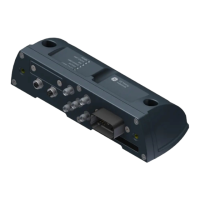
- IVU Models: PROD0842 and PROD0847.
- Display Unit: PROD0839A, featuring a 7" High Brightness LCD Touch Screen with auto-dimming, voice and tone output, light sensor for automatic screen dimming, and an LED for system status indication.
- Antenna Types and Frequencies:
- V2V (PROD0852, PROD0874): 50 Ω impedance, +3dBi gain, 902-928MHz (PROD0852) and 821-896MHz (PROD0874).
- GPS (MISC0467, PROD1222): 50 Ω impedance, +17 to +50 dB gain, L1 (1559-1610MHz), L2 (1164-1215MHz) for GPS; E1 (1559-1610MHz), E5 (1164-1215MHz) for Galileo; B1L (1559-1610MHz) for BDS; G1 (1559-1610MHz), G2 (1215-1300MHz) for GLONASS.
- GSM/3G (PROD0854): 50 Ω impedance, 0dBi, +1.7dBi, +2.9dBi gain, 700, 800, 850, 900, 1800, 1900, 2100, 2600 MHz.
- Wi-Fi (PROD0833): 50 Ω impedance, +3.0dBi gain, 2400-2484MHz.
- Power Requirements: 24VDC power, protected by 4A resettable circuit breakers for Ignition and VIN+. The IVU can remain powered for up to 14 hours after input power is isolated.
- Storage Temperature: -30 °C to +85 °C in a dry, low humidity location.
- Antenna Spacing: Minimum 300mm between V2V and GPRS antennas.
- Antenna-Occupant Distance: Minimum 37 cm from occupants to comply with MPE Radiation Regulations.
- Electrical Connections: 24-way Deutsch connector for vehicle electrical connections, 12-way Deutsch connector for display, and various coaxial connectors for antennas.
- Internal Components: The IVU contains a Lithium Ion battery.
Usage Features:
- Display Interface: The display unit shows a status bar (current system components status), approaching vehicle information (ID, speed, indicator, distance), and your vehicle information (ID, speed, indicator). Special function buttons provide access to Menu, Configuration, GPS Data, and Camera selection.
- Configuration: The system is configured via the display unit's touch screen. This includes setting the asset name (vehicle ID), asset type (make/model), object type (e.g., Heavy Vehicle Truck, Shovel), IVU orientation, and GPS antenna location (length, width, height relative to the vehicle's front left corner). For shovels, specific settings include rotation point from front and boom length.
- Network Settings: Allows manual assignment of static IP addresses for Wi-Fi and Ethernet, including masks and gateways, to avoid conflicts and ensure proper network communication.
- Self-Test Functionality: For shovel configurations, a "Self-Test" tab is used to configure and test a secondary GPS node, ensuring V2V signal strength and synchronization of RX/TX values.
- Troubleshooting: Flowcharts are provided for diagnosing "No power / Blank screen," "GPS problems," and "V2V problems" based on LED indicators and display icons.
Maintenance Features:
- Scheduled Servicing: Recommended every 6 months or 1500 hours (whichever comes first), performed by trained and authorized personnel.
- Software Updates: Automatically pushed to all IVUs connected to the CAS server and scheduled with the end-user.
- Display Unit Maintenance:
- Clean screen surface with a dry soft cloth (avoid solvents).
- Check for physical damage.
- Ensure cable connector is securely tightened (finger-tight only).
- Verify mounting bracket is secure (finger-tight only).
- System Maintenance:
- Visually inspect all antennas for good condition and ensure cables are connected.
- Check for loose or damaged cables.
- Verify system is working correctly before recommencing operations.
- Antenna Cable Terminations: Detailed instructions for stripping cables (RG58 TNC, RG58 N, RG214 TNC, RG214 N), installing ferrules and contacts, soldering, and applying heatshrink to prevent moisture ingress.
- Antenna Cable Testing: Procedures for checking continuity and short circuits using a multi-meter (open circuit >10MΩ between inner and outer conductors, low resistance <1Ω when shorted). SWR (Standing Wave Ratio) testing with a 50Ω dummy load is recommended, aiming for SWR around 1 in the 800MHz to 2.6GHz range.
- Antenna Cable Connection Security: Emphasizes tightening connections, applying self-amalgamating tape for environmental protection, and avoiding electrically insulative thread locking compounds on threads to maintain conductivity.
- Decommissioning and Disposal: System removal should be authorized by the vehicle owner and performed by a qualified Auto Electrician. All components and wiring must be removed, and vehicle wiring restored. The IVU, containing a Lithium Ion battery, must be disposed of according to local regulations, not as general waste.