Maintenance GPS 8500 / GPS 9700
40
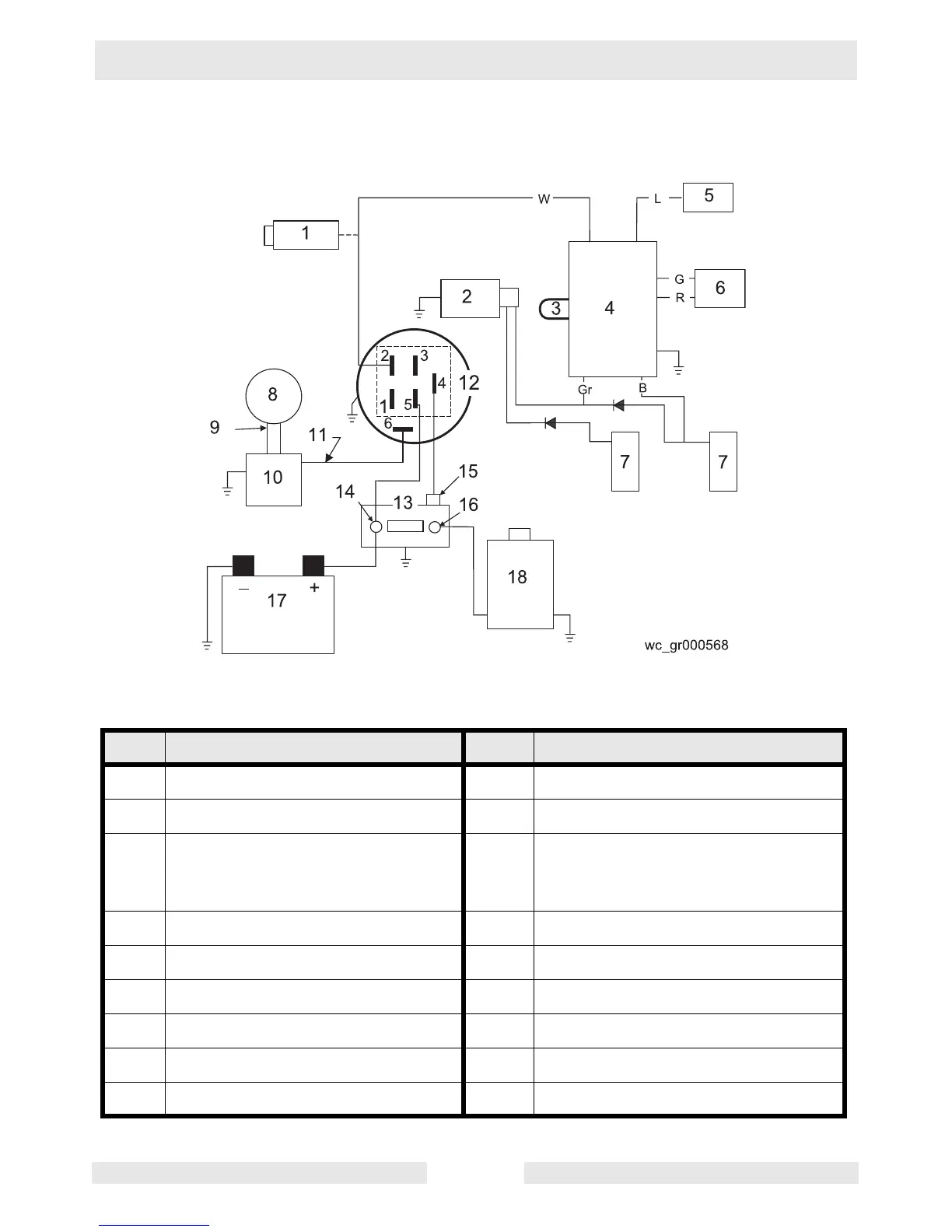
3.14 Engine Wiring Diagram
Ref. Description Ref. Description
1 Carburetor solenoid 10 Regulator rectifier
2 Stop switch terminal 11 DC output wire
3 50 Hz. loop
(GPS 8500=yellow,
GPS 9700=red)
12 Key switch
4 Module 13 Solenoid
5 Idle down device 14 Battery terminal
6 Actuator 15 Solenoid tab terminal
7 Ignition coils 16 Starter terminal
8 Alternator 17 Battery
9 AC output wires 18 Starter motor