CAPACITIES: 2 TO 100 LB
TENSION & COMPRESSION
DUAL GRADUATIONS
PEAK FORCE HOLD
EASY-TO-READ 2" DIAL
ACCURACY: ± 0.3% F.S.
AMERICAN STANDARD THREADS
■
■
■
■
■
■
■
ACCESSORIES
FD/HDL Handles
FD/RT Rubber Tip
FD/HS Hinged Hook - Small
FD/HL Hinged Hook - Large
FD/CS Hinged Cradle - Small
FD/CL Hinged Cradle - Large
FD/A-1 Aluminum Hook - Small
FD/A-2 Flat Head
FD/A-3 Cone Point
FD/A-4 Chisel Head
FD/A-5 Vee Tip
FD/A-6 Extension Rod
MODEL CAPACITY/GRADUATION
FDL 2 2 lb x 0.02 lb 1 kg x 0.01 kg
FDL 6 6 lb x 0.05 lb 3 kg x 0.025 kg
FDL 10 10 lb x 0.1 lb 5 kg x 0.05 kg
FDL 20 20 lb x 0.2 lb 10 kg x 0.1 kg
FDL 40 40 lb x 0.25 lb 20 kg x 0.2 kg
FDL 60 60 lb x 0.5 lb 30 kg x 0.25 kg
FDL 100 100 lb x 1 lb 50 kg x 0.5 kg
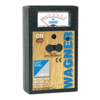
The Wagner Force Dial™ Model FDL features dual
graduations and an ergonomic design. It is available in
seven models with dual graduations in pounds and
kilograms ranging from 2 through 100 pounds and an
impressive ±0.3% accuracy.The FDL mounts directly onto
Wagner test stands and since mounting holes on the FDL
are American standard threads, it is easily mounted onto
other single column test stands with optional mounting
adapters. Optional handles and a variety of gripping
fixtures are available.
OPERATION
•Prior to using the FDL, the accuracy should be
verified by testing with weights - see “CALIBRA-
TION” section.
•Forces must be applied to the load shaft only in an
axial manner. Applying a load at an angle can cause
an error in readings and possibly damage the gage.
•Force measurements can be made with the FDL
in any position - pull at the top and push at the
bottom - since changes in the pointer’s zero
system due to the effect of gravity are compen-
sated by rotating the dial bezel.
• Attachments installed on the shaft should be
tightened by finger. Use of a tool may create a
torque load on the shaft causing internal damage
to the gage.
• Lubrication of the FDK/FDN is not recommended
since oil will accumulate dust resulting in
increased friction and decreased accuracy.
• Use of the FDL below 25% of full scale may pro-
duce inaccurate results. Another model with a lower
capacity may be necessary. The FDL is built to the
accuracy stated herein, but may be used in the
lower range of the dial if the gage is tested in that
range and found to meet user requirements.
• Call Wagner Instruments with questions regarding
the use of the FDL in your application.
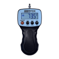
PEAK FORCE HOLD
• The maximum force applied to the FDL may be
retained for convenient reading by use of the
maximum reading hold switch located on the
upper right side of the gage. The peak reading is
saved by the pointer remaining at the maximum
force applied after the force has been removed.
To activate the peak feature press the switch to
“ON”. To release the peak and return the pointer
to zero, press the switch to “OFF”.
CALIBRATION
• The overall accuracy of the FDL is ±0.3% of full
scale. To calculate the possible error in lb or kg of
your FDL multiply the gage capacity by .003.
Example for an FDL 100:
100 lb x 0.003 = ± 0.3 lb
Thus, the possible error can be ±0.3 lb at any
reading on the dial from 0-100 lb.
•Prior to shipping, the FDL is calibrated with certified
test weights. Since rough handling during shipment
may affect the accuracy of the FDL, it is recom-
mended that the accuracy be verified prior to use by
suspending one or more known weights on the FDL.
•Periodical testing of the FDL accuracy should
be performed with certified test weights. It is sug-
gested that weights be suspended on the securely
mounted gage at 1/4, 1/2, 3/4 and full capacity.
• Do not attempt to re-calibrate the FDL. If
it is found inaccurate contact Wagner Instruments.
• When using the FDL, position the pointer by
rotating the dial to the “ZERO” position before
applying force to the gage.
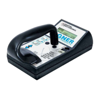
MOUNTING
• Mounting holes are provided on the rear surface
of the FDL for mounting the gage to a test stand
or fixtures. The mounting hole pattern is compat-
ible with many existing test stands. The pattern
contains 2 #10-32 threaded holes, 2 1/4 ” apart
on the vertical centerline. A third 3/16” unthreaded
clearance hole is provided for a dowel pin, found
on some test stands for suspension of the force
gage. Mounting screws should not penetrate the
gage by more than 5/16”.
FORCE DIAL™
MODEL FDL FORCE GAGE
Artisan Technology Group - Quality Instrumentation ... Guaranteed | (888) 88-SOURCE | www.artisantg.com
 Loading...