Do you have a question about the WAGO 750-455 and is the answer not in the manual?
Details document applicability, copyright, and usage restrictions.
Explains the meaning of various warning and informational symbols used in the document.
Defines number notation and explains font styles used for clarity.
Covers legal aspects, personnel qualifications, and compliance with provisions.
Details device specifications and provides essential safety precautions for installation and operation.
Highlights critical safety precautions for handling and installing the device, including specific warnings.
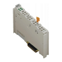
Provides an overview of the module's physical layout and identifies key components.
Details data contacts, internal bus, and CAGE CLAMP® connectors for wiring.
Explains the function of power jumper contacts for supply and transmission of power.
Describes the CAGE CLAMP® connectors used for signal input and common ground connections.
Describes the function of the LED indicators for each input channel.
Notes the absence of any operating elements on the I/O module 750-455.
Presents the electrical schematic diagram of the analog input module.
Provides detailed technical specifications for device, supply, communication, inputs, connection, and environment.
Lists the various approvals and certifications granted to the I/O modules.
Outlines the EMC and marine application standards and guidelines the I/O modules meet.
Explains how the I/O module transmits process data and provides examples of numeric value interpretation.
Describes the procedure for mounting I/O modules on a carrier rail, including sequence and precautions.
Provides step-by-step instructions for safely inserting and removing I/O modules from the assembly.
Explains how to connect conductors to CAGE CLAMP® terminals.
Provides an example illustrating the connection of signal lines to the module.
Illustrates marking examples for ATEX, IEC-Ex, and NEC 500 compliance on I/O modules.
Outlines the requirement to follow valid national and international installation rules in hazardous areas.
Details specific conditions for safe use according to ATEX, IEC-Ex, and ANSI/ISA standards for hazardous locations.
| Brand | WAGO |
|---|---|
| Model | 750-455 |
| Category | I/O Systems |
| Language | English |