Do you have a question about the WAGO 750-872/020-000 and is the answer not in the manual?
| Manufacturer | WAGO |
|---|---|
| Series | 750 |
| Item Number | 750-872/020-000 |
| Fieldbus | Ethernet |
| Programming | IEC 61131-3 |
| Supply Voltage | 24 V DC |
| Current Consumption | 500 mA |
| Operating Temperature | 0 … +55 °C |
| Bus System | Ethernet |
| Data Transfer Rate | 10/100 Mbit/s |
| Power Consumption | 12 W |
| Protection Class | IP20 |
| Connection Technology | CAGE CLAMP® |
| Number of I/O Modules | 64 |
| Relative Humidity | 95% (non-condensing) |
| Temperature Range | +55 °C |
Describes the controller's purpose and application in telecontrol systems.
Outlines the manual's content, covering technical details, installation, and configuration.
Covers copyright, personnel qualification, and conforming use of the WAGO-I/O-SYSTEM 750.
Provides critical safety instructions for device handling, installation, and operation.
Highlights essential notes and considerations for initial device setup and operation.
Provides an overview of the modular I/O system and its components.
Details mechanical, electrical, and environmental specifications of the system.
Details physical installation requirements and assembly procedures for system components.
Covers system and field power supply requirements and configurations.
Explains essential grounding procedures for the system's safety and integrity.
Explains the importance of shielding for signal integrity and electromagnetic interference reduction.
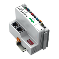
Introduces the specific controller model, its capabilities, and features.
Details the controller's functions, programming tools (WAGO-I/O-PRO CAA), and supported protocols.
Describes the physical components and interfaces of the controller.
Explains the function of the mode selection switch (Run, Stop, Reset) on the controller.
Covers the controller's startup process and program execution cycles.
Details the controller's initialization sequence upon power-up or hardware reset.
Explains how data is transferred between the controller, modules, and network.
Details how I/O modules and controller variables are addressed within the system.
Lists the memory address partitions for different data types and protocols.
Step-by-step guide for initial fieldbus node configuration and startup.
Procedure for IP assignment using WAGO Ethernet Settings for node startup.
Procedure for IP assignment using the WAGO BootP server for node startup.
Using WAGO-I/O-PRO CAA for controller programming and configuration.
Methods for transferring IEC 61131-3 application programs to the PFC.
Navigating and utilizing the controller's web interface for status and configuration.
Configuring the SNMP protocol for network management and monitoring.
Visual display of the controller and node operating status using LEDs.
Display of fault codes via the 'I/O' LED blink patterns.
Describes how the system responds to detected faults and errors.
Handling of fieldbus communication interruptions and watchdog timeouts.
Comprehensive list of technical specifications for the fieldbus controller.
General overview of Ethernet technology as a fieldbus communication method.
Basic principles and regulations for designing Ethernet networks.
Explains communication protocols and their layering within the network stack.
Details important protocols like IP, TCP, UDP, and ARP.
Details IP addressing, classes, subnetting, and key data.
Explains TCP's role in secure, connection-oriented data transport with acknowledgments.
Describes UDP's efficient, connectionless data transport without monitoring mechanisms.
Lists protocols used for system management and diagnosis.
Mechanism for assigning IP addresses via MAC-ID for network nodes.
Dynamic IP configuration using a DHCP server.
Details the MODBUS protocol and its specific functions for data exchange.
Details MODBUS function codes for requests, responses, and error handling.
Reads the status of individual input or output bits (coils).
Writes a single output bit's state to a slave device.
Writes a sequence of registers in word format to a slave device.
Displays MODBUS addresses and corresponding IEC61131 addresses for process data.
Details internal controller registers for watchdog, configuration, and firmware information.
Monitors data transfer and detects fieldbus communication failures.
Introduction to the EtherNet/IP standard and its role in industrial communication.
Describes the object model used for EtherNet/IP network communication.
Lists supported CIP Common Classes and WAGO-specific Classes for EtherNet/IP.
Attributes and services related to TCP/IP interface configuration.
Object definition for discrete input points within the EtherNet/IP system.
General overview of available I/O modules for the WAGO-I/O-SYSTEM 750.
Lists and describes various digital input modules available for the system.
Lists and describes various digital output modules available for the system.
Lists and describes various analog input modules available for the system.
Lists and describes various analog output modules available for the system.
Lists specialized I/O modules like counters, serial interfaces, and DALI masters.
Describes how process data is structured and mapped for MODBUS/TCP communication.
Describes how process data is structured and mapped for EtherNet/IP communication.
Testing MODBUS functionality using PC applications and demo versions.
Using SCADA software for process visualization and control.
Describes primary and secondary explosion protection methods.
Explains European standards (CENELEC/IEC) for classifying explosive atmospheres.
Classifies explosive environments into zones based on atmosphere type and probability.
Describes measures taken to prevent ignition of explosive atmospheres.
Outlines North American (NEC) classifications for hazardous locations and divisions.
Defines temperature limits for components in hazardous areas according to NEC.
Outlines mandatory installation rules, especially for Ex-approved systems and hazardous areas.
A beginner's guide to TCP/IP and Ethernet concepts.
A guide focused on troubleshooting network issues and problems.
Topics related to accessing system functions or data.
Topics related to Ethernet, hardware, IP, and TCP addresses.
Index entries related to system configuration.
Index entries for MODBUS Function Code FC1.
Index entries related to IP address configuration and usage.
Index entries related to internal controller variables.
Index entries related to watchdog configuration and status.