Do you have a question about the WAGO 750-871 and is the answer not in the manual?
Specifies the applicability of this documentation to the ETHERNET TCP/IP 2-port Controller (750-871).
Details copyright information and usage restrictions for the manual, prohibiting unauthorized reproduction or distribution.
Explains the meaning of various symbols (DANGER, WARNING, NOTICE, NOTE) and font conventions used in the documentation.
Defines the notation conventions for decimal, hexadecimal, and binary numbers used throughout the manual.
Outlines the use of different font types (italic, bold, inverted commas) to indicate specific elements like paths, menus, and values.
Covers legal aspects including subject to changes, personnel qualifications, and compliance with underlying provisions.
Details the factory hardware and software configurations and liability for changes or non-compliant usage.
Provides critical safety precautions for installation and operation, including danger warnings, handling, and cleaning notices.
Specifies conditions for using Ethernet devices, including network security, access restrictions, and firewall recommendations.
Details on manufacturing number, hardware address (MAC ID), and component updates for the system.
Guidelines for proper storage, assembly procedures, and transportation of the devices.
Explains power supply requirements, isolation, system supply, and field supply connections.
Details grounding procedures for DIN rail and function, and methods for shielding bus and signal lines.
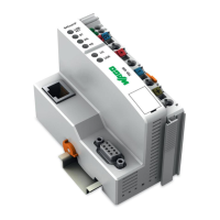
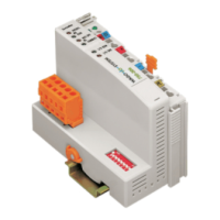
Provides a visual overview of the device and describes its various connectors.
Details device supply requirements and fieldbus connection interfaces.
Details the function and meaning of display elements (LEDs) and operating controls (switches).
Presents detailed technical specifications, device data, supply information, approvals, and applicable standards.
Specifies the recommended installation orientation and overall setup during mounting.
Instructions for mounting the device onto a carrier rail, including rail properties and spacing.
Details the correct sequence for mounting devices in the system.
Step-by-step instructions for inserting and removing fieldbus couplers, controllers, and I/O modules.
Explains the data contacts and internal bus connections within the system.
Details the power contacts and how to connect the field supply.
Provides instructions on how to properly connect conductors using the CAGE CLAMP® system.
Describes the operating system of the controller, including run-up and PFC cycle.
Explains the structure of process data for MODBUS/TCP and EtherNet/IP.
Details how data is exchanged between different components and protocols.
Instructions for connecting a client PC to the fieldbus nodes.
Methods for assigning IP addresses to the fieldbus node, including DHCP and BootP server configurations.
Procedures for testing the correct functionality of the fieldbus node.
Steps involved in preparing the flash file system for the device.
Information on synchronizing the device's real-time clock.
Instructions on how to restore the device to its factory default settings.
Steps for configuring the fieldbus controller using the WAGO I/O Configurator tool.
Details on the Ethernet libraries available for WAGO-I/O-PRO programming.
Outlines any functional limitations or constraints of the programming environment.
Provides general information and context regarding IEC tasks in programming.
Information on managing and handling system events within the controller.
Instructions for transferring the programmed IEC application to the controller.
Settings for Ethernet, TCP/IP, and Port configuration via the WBM.
Configuration of Watchdog, Clock, Security, PLC, I/O, and WebVisu via WBM.
Options for configuring SNMP (Simple Network Management Protocol) and associated settings.
Explanation of LED indicators for signaling status and diagnostics.
Describes how the device behaves and indicates faults, including loss of fieldbus or internal failures.
Provides foundational information about Ethernet communication principles, architecture, and terms.
Details IP, TCP, UDP, and configuration/diagnostic protocols like DHCP, DNS, BootP, HTTP.
Information about the SNMP protocol, MIB descriptions, and traps.
Explains the various MODBUS function codes, register mapping, and register descriptions.
In-depth description of the EtherNet/IP protocol, its characteristics, and object model.
General introduction and overview of the various I/O modules available.
Details the process data architecture for MODBUS/TCP for various digital, analog, and specialty I/O modules.
Details the process data architecture for EtherNet/IP for various digital, analog, and specialty I/O modules.
Examples demonstrating testing procedures for MODBUS protocol and fieldbus nodes.
Examples of using SCADA software for visualization and control applications.
Examples of marking configurations for hazardous environments according to ATEX, IEC-Ex, and NEC.
Regulations and guidelines for installing devices in hazardous environments.
Details specific safety conditions for using the devices in hazardous environments as per various certifications.
Details the MIB II groups, including System, Interface, IP, and TCP/UDP groups.
Lists and describes specific WAGO MIB groups for management and monitoring.
| Manufacturer | WAGO |
|---|---|
| Product Name | 750-871 |
| Category | I/O Systems |
| Series | 750 |
| Programming Language | IEC 61131-3 |
| Power Supply | 24 V DC |
| Relative Humidity | 95 % (non-condensing) |
| Protection Class | IP20 |
| Weight | Approx. 150 g |
| Communication Protocols | EtherCAT |
| Number of I/O Modules | System Dependent |
| Operating Temperature | -25 to +60 °C |
| Storage Temperature | -40 °C to +85 °C |
| Dimensions (W x H x D) | 100 mm |
| Dimensions | 100 mm |
| Data Transfer Rate | 10/100 Mbit/s |