Do you have a question about the WAGO I/O SYSTEM 750 750-833 and is the answer not in the manual?
Covers copyright, personnel qualifications, and conforming use of the devices.
Outlines copyright provisions for the manual and WAGO's rights.
Details required qualifications for using the product safely.
Provides an overview of the modular WAGO I/O SYSTEM 750, its components, and functionality.
Details carrier rail properties and guidelines for mounting components.
Explains the three electrically isolated potentials within the field bus node.
Details how the system supply is connected via clamps and its voltage protection.
Details how sensors/actuators connect and how power is passed via jumper contacts.
Details framework assembly and insulated assembly for grounding the DIN rail.
Discusses reducing interferences and improving signal quality through shielding.
Refers to assembly guidelines for bus conductor shielding.
Mentions shield connection for analog and interface bus modules.
Describes the controller's function, programming with WAGO-I/O-PRO, and key features.
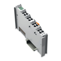
Shows a view of the controller and lists its main components like device supply and bus connection.
Explains how the device supply is fed via clamps and its role in providing voltage.
Details the PROFIBUS interface as a D-Sub connection and its pin assignments.
Explains the function of LEDs (RUN, BF, DIA, BUS, I/O, USR) for status indication.
Describes how the station address is set using two decimal rotary switches.
Locates the interface behind the cover flap for communication and firmware transfer.
Details the push/slide switch with settings for RUN, STOP, bootstrap, and hardware reset.
Describes the controller's startup sequence after power-on or hardware reset, including LED indications.
Explains the PFC cycle, including reading inputs/outputs, processing, and updating times.
Explains how the process is mapped on PROFIBUS and the generation of an internal local process image.
Describes data exchange via PROFIBUS and internal mapping of input/output data.
Explains how process data structure depends on the coupler and transmission format.
Lists the three interfaces for data exchange: field bus, PLC, and bus modules.
Describes memory spaces for physical I/O data and PFC variables.
Explains direct CPU access to bus terminal data via absolute addresses.
Lists field bus variables and their addresses up to SW 02 and from SW 03.
Describes flags and their addresses; notes they are non-volatile.
Explains how to calculate bit, byte, and dword addresses based on word addresses.
Provides examples of absolute addresses for inputs, outputs, and flags.
Introduces libraries for IEC 61131-3 programming and specific PROFIBUS libraries.
Explains program transfer methods via serial or field bus interfaces.
Details the physical connection and software configuration for serial interface program transfer.
Outlines program transfer via the field bus using a suitable communication driver.
Describes communication using 2-byte I/O data and configuration requirements.
Explains MSAC2 interface communication for program download and debugging.
Explains how to configure the node based on physical requirements of controllers and I/O modules.
Details configuring memory area based on field bus variable arrangement.
Explains GSD files for PROFIBUS DP device features and configuration software.
Describes identification bytes containing information about input/output structure and scope.
Lists identification bytes for bus controller modules.
Refers to chapter 5.3 for identification bytes of all I/O modules.
Provides an example application of a field bus node with controller and I/O modules.
Details the process data channel for PFC interface and its implicit allocation.
Refers to chapter 5.4 for a list of all I/O modules and their parameters.
Refers to EN 50170 for station status information.
States the master address is located in byte 3 of slave diagnostics.
Explains manufacturer identification is in bytes 4 and 5 as a 16-bit code.
Describes identification-based diagnostics covering connected modules and their status.
Details device status information including header, type, slot, differentiation, message, and argument.
Lists internal status messages and arguments for faults like EEPROM check sum and overflow.
Lists internal bus status messages and arguments for commands and interruptions.
Lists PROFIBUS DP status messages for parameter and configuration errors.
Lists PFC-RTS status messages with descriptions.
Describes channel-based diagnostics structure with header, signal type, channel number, and fault type.
Categorizes fault types for I/O modules, distinguishing standardized and WAGO-specific faults.
Lists fault cases for various I/O modules based on item number, channel type, and fault type.
Explains parameterization status for PROFIsafe I/O modules during DP Master startup.
Lists PROFIsafe parameterization faults and their corresponding meanings.
Explains addressing data areas via index and module number, including warnings for writing.
Lists index, meaning, and service primitives/data length for field bus coupler slots 0 and 1.
Details index and meaning for complex I/O modules, including tables and error messages.
Lists index and meaning for binary I/O modules, covering channel information and examples.
Describes how blink codes display fault messages using sequences, fault codes, and arguments.
Explains the meaning of the upper four LEDs (RUN, BF, DIA, BUS) and provides a table of status and remedies.
Details fault codes, descriptions, and remedies related to the BUS LED blink codes.
Explains the I/O LED's role in indicating node operation and faults, including status descriptions.
Lists fault messages via I/O LED blink codes, including hardware, configuration, and data faults.
Explains the status of system and field supply LEDs (A, B, C) and their remedies.
Describes field bus failure scenarios, BF-LED indication, and substitute value strategies.
Explains internal bus faults, I/O-LED indication, and automatic restart behavior.
Defines PROFIBUS as an open field bus standard for fast data exchange between control and peripherals.
Defines PROFIBUS as an open field bus standard for fast data exchange between control and peripherals.
Details PROFIBUS wiring specifications including line type A, parameters, and transmission speed vs. segment length.
Provides an overview of available bus modules for WAGO-I/O-SYSTEM 750 applications.
Lists various digital input modules categorized by voltage and channel count.
Lists various digital output modules categorized by voltage, current, and features.
Lists analog input modules by current and voltage ranges, including special types.
Lists analog output modules by current and voltage ranges.
Lists various special modules like counter, frequency measuring, and interface modules.
Lists system modules like bus extensions, power supplies, filters, and end modules.
Details how process data is structured for PROFIBUS-DP, including status, control, and data bytes.
Details process image length in bits for 2 DI modules based on diagnostics information.
Details process image length in bits for 4 DI modules based on diagnostics information.
Details process image length in bits for 8 DI modules based on diagnostics information.
Details process image length in bits for 16 DI modules.
Details process image length in bits for 2 DO modules based on diagnostics information.
Details process image length for 2 DO modules with diagnostics based on bit count.
Details process image length for 4 DO modules.
Details process image length for 4 DO modules with diagnostics.
Details process image length for 8 DO modules.
Details process image length for 8 DO modules with diagnostics.
Details process image length for 16 DO modules.
Details process image length for power supply modules with diagnostics.
Details process image length and mapping for 2 AI I/O modules.
Details process image length and mapping for 4 AI I/O modules.
Details process image length and mapping for 2 AO I/O modules.
Details process image length and mapping for 4 AO I/O modules.
Details process image length and mapping for counter modules 750-404 and 750-638.
Details process image length and mapping for the PWM module 750-511.
Details process image length and mapping for the Stepper Controller.
Details module identification, process image, and parameters for the SSI Encoder Interface.
Details process image length and mapping for encoder interfaces and serial interfaces.
Details process image length and mapping for the Digital Impulse Interface.
Details module identification, process image, and parameters for Serial Interfaces.
Details module identification, process image, and parameters for the Data Exchange Module.
Details module identification, process image, and parameters for the DALI/DSI Master.
Details module identification, process image, and parameters for the AS Interface Master.
Details module identification, process image, and parameters for PROFIsafe I/O Modules.
Lists PROFIBUS identification bytes for binary input modules, including module, description, and identification values.
Lists PROFIBUS identification bytes for binary output modules.
Lists PROFIBUS identification bytes for supply modules.
Lists PROFIBUS identification bytes for analog input modules.
Lists PROFIBUS identification bytes for analog output modules.
Lists PROFIBUS identification bytes for special modules like counters and interfaces.
Lists field bus variables and their PFC module allocation, including input and output variables.
Lists PFC input variables allocated up to SW 02 and their corresponding PFC module addresses.
Lists PFC output variables allocated from SW 03 with data type identification.
States that all binary I/O modules contain extended parameterization information for identification and mapping.
Details module identification, process image, and parameters for 2 DI I/O modules.
Details module identification, process image, and parameters for 2 DI modules with 1-bit diagnostics.
Details module identification, process image, and parameters for 4 DI I/O modules.
Details module identification, process image, and parameters for 8 DI I/O modules.
Details module identification, process image, and parameters for 16 DI I/O modules.
Details module identification, process image, and parameters for 2 DO I/O modules.
Details module identification, process image, and parameters for 2 DO I/O modules with 1-bit diagnostics.
Details module identification, process image, and parameters for 2 DO modules with 2-bit diagnostics.
Details module identification, process image, and parameters for 4 DO I/O modules.
Details module identification, process image, and parameters for 4 DO modules with 1-bit diagnostics.
Details module identification, process image, and parameters for 8 DO I/O modules.
Details module identification, process image, and parameters for 8 DO modules with 1-bit diagnostics.
Details module identification, process image, and parameters for 16 DO I/O modules.
Details module identification, process image, and parameters for 2 DI/DO modules with 1-bit diagnostics.
Details module identification, process image, and parameters for power supply modules with diagnostics.
Provides details on analog I/O modules, including parameterization and diagnostics.
Details module identification, process image, and parameters for 2 AI I/O modules.
Details module identification, process image, and parameters for 4 AI I/O modules.
Details module identification, process image, and parameters for 2 AO I/O modules.
Details module identification, process image, and parameters for 4 AO I/O modules.
Lists special digital modules with parameterization information for identification and mapping.
Details module identification, process image, and parameters for Counter Modules 750-404, 750-638.
Details module identification, process image, and parameters for the PWM Module 750-511.
Details module identification, process image, and parameters for the Stepper Controller.
Details interface modules for path and angle measurement, including parameterization.
Details module identification, process image, and parameters for the SSI Encoder Interface.
Details module identification, process image, and parameters for Incremental Encoder Interfaces.
Details module identification, process image, and parameters for the Digital Impulse Interface.
Details module identification, process image, and parameters for Serial Interfaces.
Details module identification, process image, and parameters for the Data Exchange Module.
Details module identification, process image, and parameters for the ENOCEAN Receiver Module.
Details module identification, process image, and parameters for the DALI/DSI Master.
Details module identification, process image, and parameters for the AS Interface Master.
Details module identification, process image, and parameters for PROFIsafe I/O Modules.
Lists index, meaning, and service primitives/data length for 2 DI I/O modules.
Lists index, meaning, and service primitives/data length for 2 DI I/O modules with diagnostics.
Lists index, meaning, and service primitives/data length for 4 DI I/O modules.
Lists index, meaning, and service primitives/data length for 8 DI I/O modules.
Lists index, meaning, and service primitives/data length for 16 DI I/O modules.
Lists index, meaning, and service primitives/data length for 2 DO I/O modules.
Lists index, meaning, and service primitives for 2 DO I/O modules with diagnostics.
Lists index, meaning, and service primitives for 4 DO I/O modules.
Lists index, meaning, and service primitives for 4 DO I/O modules with 1-bit diagnostics.
Lists index, meaning, and service primitives for 8 DO I/O modules.
Lists index, meaning, and service primitives for 8 DO I/O modules with diagnostics.
Lists index, meaning, and service primitives for 2 DI/DO I/O modules with diagnostics.
Lists index, meaning, and service primitives for supply modules with diagnostics.
Lists index, meaning, and service primitives for 2 AI I/O modules.
Lists index, meaning, and service primitives for 4 AI I/O modules.
Lists index, meaning, and service primitives for 2 AO I/O modules.
Lists index, meaning, and service primitives for 4 AO I/O modules.
Lists index, meaning, and service primitives for Counter Module 750-404.
Lists index, meaning, and service primitives for Counter Module 750-638 and PWM Module 750-511.
Lists index, meaning, and service primitives for the SSI Interface.
Lists index, meaning, and service primitives for encoder interfaces and serial interfaces.
Lists index, meaning, and service primitives for the Digital Impulse Interface.
Lists index, meaning, and service primitives for serial interfaces and data exchange modules.
Lists index, meaning, and service primitives for DALI/DSI Master.
Lists index, meaning, and service primitives for AS Interface Master.
Lists index, meaning, and service primitives for PROFIsafe I/O Modules.
Introduces the use of WAGO-I/O-SYSTEM 750 in zone 2 explosive environments.
Discusses primary and secondary explosion protection measures.
Covers classification specifications based on EN50 and IEC 60079 standards.
Explains explosive environments and zones (0, 1, 2 for gases; 20, 21, 22 for dust).
Subdivides electrical components into Group I and Group II, with IIA, IIB, IIC subdivisions.
Classifies electrical operating means by unit category, explosion group, and area of use.
Details temperature classes (T1-T6) and their maximum surface temperatures.
Explains various types of ignition protection (EEx o, p, q, d, e, m, i, n) and their applications.
Covers North American classifications according to NEC 500, including divisions and explosion protection groups.
Defines Division 1 and Division 2 based on the probability of explosive atmospheres.
Categorizes electrical components into Class I, II, and III based on hazardous materials.
Differentiates electrical components by temperature classes (T1-T6) for explosive areas.
Explains module identification labeling for European and North American standards.
Explains European identification labeling based on CENELEC and IEC standards.
Explains North American identification labeling according to NEC 500.
Lists German and North American installation regulations relevant to explosive areas.
Covers copyright, personnel qualifications, and conforming use of the devices.
Outlines copyright provisions for the manual and WAGO's rights.
Details required qualifications for using the product safely.
Provides an overview of the modular WAGO I/O SYSTEM 750, its components, and functionality.
Details carrier rail properties and guidelines for mounting components.
Explains the three electrically isolated potentials within the field bus node.
Details how the system supply is connected via clamps and its voltage protection.
Details how sensors/actuators connect and how power is passed via jumper contacts.
Details framework assembly and insulated assembly for grounding the DIN rail.
Discusses reducing interferences and improving signal quality through shielding.
Refers to assembly guidelines for bus conductor shielding.
Mentions shield connection for analog and interface bus modules.
Describes the controller's function, programming with WAGO-I/O-PRO, and key features.
Shows a view of the controller and lists its main components like device supply and bus connection.
Explains how the device supply is fed via clamps and its role in providing voltage.
Details the PROFIBUS interface as a D-Sub connection and its pin assignments.
Explains the function of LEDs (RUN, BF, DIA, BUS, I/O, USR) for status indication.
Describes how the station address is set using two decimal rotary switches.
Locates the interface behind the cover flap for communication and firmware transfer.
Details the push/slide switch with settings for RUN, STOP, bootstrap, and hardware reset.
Describes the controller's startup sequence after power-on or hardware reset, including LED indications.
Explains the PFC cycle, including reading inputs/outputs, processing, and updating times.
Explains how the process is mapped on PROFIBUS and the generation of an internal local process image.
Describes data exchange via PROFIBUS and internal mapping of input/output data.
Explains how process data structure depends on the coupler and transmission format.
Lists the three interfaces for data exchange: field bus, PLC, and bus modules.
Describes memory spaces for physical I/O data and PFC variables.
Explains direct CPU access to bus terminal data via absolute addresses.
Lists field bus variables and their addresses up to SW 02 and from SW 03.
Describes flags and their addresses; notes they are non-volatile.
Explains how to calculate bit, byte, and dword addresses based on word addresses.
Provides examples of absolute addresses for inputs, outputs, and flags.
Introduces libraries for IEC 61131-3 programming and specific PROFIBUS libraries.
Explains program transfer methods via serial or field bus interfaces.
Details the physical connection and software configuration for serial interface program transfer.
Outlines program transfer via the field bus using a suitable communication driver.
Describes communication using 2-byte I/O data and configuration requirements.
Explains MSAC2 interface communication for program download and debugging.
Explains how to configure the node based on physical requirements of controllers and I/O modules.
Details configuring memory area based on field bus variable arrangement.
Explains GSD files for PROFIBUS DP device features and configuration software.
Describes identification bytes containing information about input/output structure and scope.
Lists identification bytes for bus controller modules.
Refers to chapter 5.3 for identification bytes of all I/O modules.
Provides an example application of a field bus node with controller and I/O modules.
Details the process data channel for PFC interface and its implicit allocation.
Refers to chapter 5.4 for a list of all I/O modules and their parameters.
Refers to EN 50170 for station status information.
States the master address is located in byte 3 of slave diagnostics.
Explains manufacturer identification is in bytes 4 and 5 as a 16-bit code.
Describes identification-based diagnostics covering connected modules and their status.
Details device status information including header, type, slot, differentiation, message, and argument.
Lists internal status messages and arguments for faults like EEPROM check sum and overflow.
Lists internal bus status messages and arguments for commands and interruptions.
Lists PROFIBUS DP status messages for parameter and configuration errors.
Lists PFC-RTS status messages with descriptions.
Describes channel-based diagnostics structure with header, signal type, channel number, and fault type.
Categorizes fault types for I/O modules, distinguishing standardized and WAGO-specific faults.
Lists fault cases for various I/O modules based on item number, channel type, and fault type.
Explains parameterization status for PROFIsafe I/O modules during DP Master startup.
Lists PROFIsafe parameterization faults and their corresponding meanings.
Explains addressing data areas via index and module number, including warnings for writing.
Lists index, meaning, and service primitives/data length for field bus coupler slots 0 and 1.
Details index and meaning for complex I/O modules, including tables and error messages.
Lists index and meaning for binary I/O modules, covering channel information and examples.
Describes how blink codes display fault messages using sequences, fault codes, and arguments.
Explains the meaning of the upper four LEDs (RUN, BF, DIA, BUS) and provides a table of status and remedies.
Details fault codes, descriptions, and remedies related to the BUS LED blink codes.
Explains the I/O LED's role in indicating node operation and faults, including status descriptions.
Lists fault messages via I/O LED blink codes, including hardware, configuration, and data faults.
Explains the status of system and field supply LEDs (A, B, C) and their remedies.
Describes field bus failure scenarios, BF-LED indication, and substitute value strategies.
Explains internal bus faults, I/O-LED indication, and automatic restart behavior.
Defines PROFIBUS as an open field bus standard for fast data exchange between control and peripherals.
Defines PROFIBUS as an open field bus standard for fast data exchange between control and peripherals.
Details PROFIBUS wiring specifications including line type A, parameters, and transmission speed vs. segment length.
Provides an overview of available bus modules for WAGO-I/O-SYSTEM 750 applications.
Lists various digital input modules categorized by voltage and channel count.
Lists various digital output modules categorized by voltage, current, and features.
Lists analog input modules by current and voltage ranges, including special types.
Lists analog output modules by current and voltage ranges.
Lists various special modules like counter, frequency measuring, and interface modules.
Lists system modules like bus extensions, power supplies, filters, and end modules.
Details how process data is structured for PROFIBUS-DP, including status, control, and data bytes.
Details process image length in bits for 2 DI modules based on diagnostics information.
Details process image length in bits for 4 DI modules based on diagnostics information.
Details process image length in bits for 8 DI modules based on diagnostics information.
Details process image length in bits for 16 DI modules.
Details process image length in bits for 2 DO modules based on diagnostics information.
Details process image length for 2 DO modules with diagnostics based on bit count.
Details process image length for 4 DO modules.
Details process image length for 4 DO modules with diagnostics.
Details process image length for 8 DO modules.
Details process image length for 8 DO modules with diagnostics.
Details process image length for 16 DO modules.
Details process image length for power supply modules with diagnostics.
Details process image length and mapping for 2 AI I/O modules.
Details process image length and mapping for 4 AI I/O modules.
Details process image length and mapping for 2 AO I/O modules.
Details process image length and mapping for 4 AO I/O modules.
Details process image length and mapping for counter modules 750-404 and 750-638.
Details process image length and mapping for the PWM module 750-511.
Details process image length and mapping for the Stepper Controller.
Details module identification, process image, and parameters for the SSI Encoder Interface.
Details process image length and mapping for encoder interfaces and serial interfaces.
Details process image length and mapping for the Digital Impulse Interface.
Details module identification, process image, and parameters for Serial Interfaces.
Details module identification, process image, and parameters for the Data Exchange Module.
Details module identification, process image, and parameters for the DALI/DSI Master.
Details module identification, process image, and parameters for the AS Interface Master.
Details module identification, process image, and parameters for PROFIsafe I/O Modules.
Lists PROFIBUS identification bytes for binary input modules, including module, description, and identification values.
Lists PROFIBUS identification bytes for binary output modules.
Lists PROFIBUS identification bytes for supply modules.
Lists PROFIBUS identification bytes for analog input modules.
Lists PROFIBUS identification bytes for analog output modules.
Lists PROFIBUS identification bytes for special modules like counters and interfaces.
Lists field bus variables and their PFC module allocation, including input and output variables.
Lists PFC input variables allocated up to SW 02 and their corresponding PFC module addresses.
Lists PFC output variables allocated from SW 03 with data type identification.
States that all binary I/O modules contain extended parameterization information for identification and mapping.
Details module identification, process image, and parameters for 2 DI I/O modules.
Details module identification, process image, and parameters for 2 DI modules with 1-bit diagnostics.
Details module identification, process image, and parameters for 4 DI I/O modules.
Details module identification, process image, and parameters for 8 DI I/O modules.
Details module identification, process image, and parameters for 16 DI I/O modules.
Details module identification, process image, and parameters for 2 DO I/O modules.
Details module identification, process image, and parameters for 2 DO I/O modules with 1-bit diagnostics.
Details module identification, process image, and parameters for 2 DO modules with 2-bit diagnostics.
Details module identification, process image, and parameters for 4 DO I/O modules.
Details module identification, process image, and parameters for 4 DO modules with 1-bit diagnostics.
Details module identification, process image, and parameters for 8 DO I/O modules.
Details module identification, process image, and parameters for 8 DO modules with 1-bit diagnostics.
Details module identification, process image, and parameters for 16 DO I/O modules.
Details module identification, process image, and parameters for 2 DI/DO modules with 1-bit diagnostics.
Details module identification, process image, and parameters for power supply modules with diagnostics.
Provides details on analog I/O modules, including parameterization and diagnostics.
Details module identification, process image, and parameters for 2 AI I/O modules.
Details module identification, process image, and parameters for 4 AI I/O modules.
Details module identification, process image, and parameters for 2 AO I/O modules.
Details module identification, process image, and parameters for 4 AO I/O modules.
Lists special digital modules with parameterization information for identification and mapping.
Details module identification, process image, and parameters for Counter Modules 750-404, 750-638.
Details module identification, process image, and parameters for the PWM Module 750-511.
Details module identification, process image, and parameters for the Stepper Controller.
Details interface modules for path and angle measurement, including parameterization.
Details module identification, process image, and parameters for the SSI Encoder Interface.
Details module identification, process image, and parameters for Incremental Encoder Interfaces.
Details module identification, process image, and parameters for the Digital Impulse Interface.
Details module identification, process image, and parameters for Serial Interfaces.
Details module identification, process image, and parameters for the Data Exchange Module.
Details module identification, process image, and parameters for the ENOCEAN Receiver Module.
Details module identification, process image, and parameters for the DALI/DSI Master.
Details module identification, process image, and parameters for the AS Interface Master.
Details module identification, process image, and parameters for PROFIsafe I/O Modules.
Lists index, meaning, and service primitives/data length for 2 DI I/O modules.
Lists index, meaning, and service primitives/data length for 2 DI I/O modules with diagnostics.
Lists index, meaning, and service primitives/data length for 4 DI I/O modules.
Lists index, meaning, and service primitives/data length for 8 DI I/O modules.
Lists index, meaning, and service primitives/data length for 16 DI I/O modules.
Lists index, meaning, and service primitives/data length for 2 DO I/O modules.
Lists index, meaning, and service primitives for 2 DO I/O modules with diagnostics.
Lists index, meaning, and service primitives for 4 DO I/O modules.
Lists index, meaning, and service primitives for 4 DO I/O modules with 1-bit diagnostics.
Lists index, meaning, and service primitives for 8 DO I/O modules.
Lists index, meaning, and service primitives for 8 DO I/O modules with diagnostics.
Lists index, meaning, and service primitives for 2 DI/DO I/O modules with diagnostics.
Lists index, meaning, and service primitives for supply modules with diagnostics.
Lists index, meaning, and service primitives for 2 AI I/O modules.
Lists index, meaning, and service primitives for 4 AI I/O modules.
Lists index, meaning, and service primitives for 2 AO I/O modules.
Lists index, meaning, and service primitives for 4 AO I/O modules.
Lists index, meaning, and service primitives for Counter Module 750-404.
Lists index, meaning, and service primitives for Counter Module 750-638 and PWM Module 750-511.
Lists index, meaning, and service primitives for the SSI Interface.
Lists index, meaning, and service primitives for encoder interfaces and serial interfaces.
Lists index, meaning, and service primitives for the Digital Impulse Interface.
Lists index, meaning, and service primitives for serial interfaces and data exchange modules.
Lists index, meaning, and service primitives for DALI/DSI Master.
Lists index, meaning, and service primitives for AS Interface Master.
Lists index, meaning, and service primitives for PROFIsafe I/O Modules.
Introduces the use of WAGO-I/O-SYSTEM 750 in zone 2 explosive environments.
Discusses primary and secondary explosion protection measures.
Covers classification specifications based on EN50 and IEC 60079 standards.
Explains explosive environments and zones (0, 1, 2 for gases; 20, 21, 22 for dust).
Subdivides electrical components into Group I and Group II, with IIA, IIB, IIC subdivisions.
Classifies electrical operating means by unit category, explosion group, and area of use.
Details temperature classes (T1-T6) and their maximum surface temperatures.
Explains various types of ignition protection (EEx o, p, q, d, e, m, i, n) and their applications.
Covers North American classifications according to NEC 500, including divisions and explosion protection groups.
Defines Division 1 and Division 2 based on the probability of explosive atmospheres.
Categorizes electrical components into Class I, II, and III based on hazardous materials.
Differentiates electrical components by temperature classes (T1-T6) for explosive areas.
Explains module identification labeling for European and North American standards.
Explains European identification labeling based on CENELEC and IEC standards.
Explains North American identification labeling according to NEC 500.
Lists German and North American installation regulations relevant to explosive areas.
| Brand | WAGO |
|---|---|
| Model | I/O SYSTEM 750 750-833 |
| Category | I/O Systems |
| Language | English |