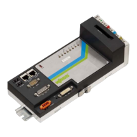
Do you have a question about the WAGO WAGO-I/O-IPC-C6 and is the answer not in the manual?
| Ethernet | 2 x 10/100/1000 Mbps |
|---|---|
| Display Outputs | HDMI |
| Operating System | Linux |
| Power Supply | 24 V DC |
| HDMI | 1 |
| Fieldbus | PROFINET, EtherNet/IP, Modbus TCP |
| Operating Temperature | 0 … +55 °C |
| Protocols | PROFINET, EtherNet/IP, Modbus TCP |
| Serial Interface | RS-232/485 |
Specifies the validity scope of the operating instructions for the WAGO-I/O-IPC-C6.
Details copyright protection and usage restrictions for the manual.
Explains various warning, caution, and note symbols used in the documentation.
Defines the number notation conventions used throughout the document.
Explains the font conventions used for different elements like paths, menu items, and buttons.
Covers legal aspects including subject to changes, patents, and third-party products.
Provides crucial safety advice and precautions for operating and handling the I/O-IPC and related components.
Details the safety equipment and protection class (IP20) of the 750 Series components.
Offers guidance on operational considerations, including electromagnetic interference protection and 24V supply.
Outlines specific conditions and recommendations for using ETHERNET devices, including security measures.
Lists the components included in the standard delivery package of the I/O-IPC.
Provides a general description of the I/O-IPC automation device and its capabilities.
Details the physical interfaces of the I/O-IPC, their positions, and functions.
Explains the function of LEDs and describes the physical operating elements of the I/O-IPC.
Presents comprehensive technical data and lists granted conformity and Ex approvals for the I/O-IPC.
Lists applicable standards and guidelines, focusing on electromagnetic compatibility.
Explains the functionality of the two RJ-45 ETHERNET interfaces and their LEDs.
Describes the interface for providing 24V electronic power supply to the I/O-IPC and modules.
Details the PROFIBUS interface and describes the USB interfaces for connecting USB devices.
Explains the integrated digital I/O connector and the RS-232 serial interface for console access.
Explains the DVI-I interface for monitors and CoDeSys visualizations.
Provides essential safety and installation/removal guidelines for the I/O-IPC.
Details mounting directions and instructions for securing the I/O-IPC onto a DIN rail.
Explains connecting I/O modules and the process for safely removing the I/O-IPC.
Provides safety notes regarding electric voltage and interruption of the supply voltage.
Lists required accessories and details power supply via 750-602 and 750-626 modules.
Lists prerequisites and steps for turning on the I/O-IPC and starting the operating system and CoDeSys.
Explains IP address setup using BootP and testing network connectivity via ping.
Provides instructions for switching off and restarting the I/O-IPC, including safety precautions.
Explains how to configure the I/O-IPC using HTML pages via a web browser.
Details configuring the I/O-IPC via ETHERNET (Telnet) or RS-232 using the IPC Configuration Tool.
Explains how to configure the I/O-IPC using a directly connected monitor and keyboard.
Explains how to access process data and the structure of MODBUS telegrams.
Lists MODBUS function codes for accessing process image data for inputs and outputs.
Describes configuring the I/O-IPC and reading information using the MODBUS configuration register.
Provides an example to clarify process image access with I/O modules.
Explains process images, their structure, and the syntax for logical addresses.
Details how to access process images for inputs and outputs via CoDeSys 2.3.
Illustrates addressing examples for accessing process images with I/O modules.
Guides on installing the CoDeSys 2.3 programming system onto the I/O-IPC.
Provides steps for creating a first CoDeSys project, including function blocks and configuration.
Explains task configuration, priorities, synchronization, and system events.
Covers the creation and execution of CoDeSys visualizations (HMI, Web, Target).
Guides on integrating PROFIBUS-I/O-IPC into PLC configuration and calling addresses/symbolic names.
Details setting choices for PROFIBUS master: base parameters and DP parameters.
Explains declaring variables for accessing PROFIBUS I/O module inputs and outputs.
Guides on transferring and logging in the PLC program to the I/O-IPC.
Describes creating diagnostics using fieldbus master and releasing channel diagnostics.
Demonstrates linking a dynamic library using a C-function in CoDeSys.
Covers special features like data types and structures for C-functions.
Explains starting Linux programs or scripts using C-functions and encapsulation.
Introduces the different types of I/O modules available for the WAGO-I/O-SYSTEM 750.
Explains the process image structure for various WAGO I/O modules with MODBUS/TCP.
Details the process image mapping for various digital input and output modules.
Describes the process image mapping for analog input and output modules.
Covers various specialty I/O modules like Counter, Pulse Width, and Serial Interface modules.
Details the WAGOConfigToolLIB.lib library for configuring and parameterizing the I/O-IPC.
Describes the WagoLibNetSnmp.lib library for creating custom OIDs and setting/querying values.
Lists configuration scripts for MODBUS/UDP, MODBUS/TCP, and MODBUS/RTU.
Details configuration scripts for general SNMP information and manager settings.





 Loading...