WAGO-I/O-SYSTEM 750 PROFIBUS Master in CoDeSys 2.3 137
758-874/000-131 WAGO-I/O-IPC-C6
Manual
Version 1.0.0
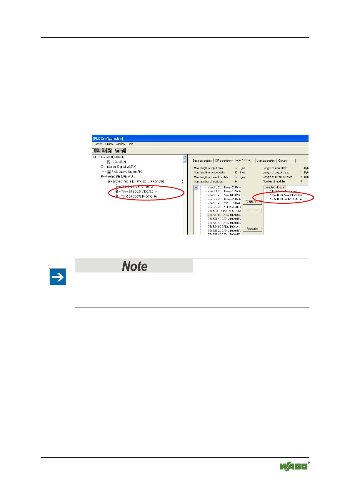
3. Click on the "Inputs/outputs" tab. The object "750-343 No process data
channel" is preset. This object may not be deleted.
4. Apply the topology of the I/O modules connected to the slave (from the
coupler to the end module) to the control configuration. Click [Select>>] to
add the respective I/O modules to the window on the right.
5. Click [Delete] to delete any I/O modules you may have added in error.
In this example, a digital input module and a digital output module are connected
to the slave.
Figure 62: Selecting I/O modules
I/O modules that do not provide any process data
I/O modules that do not provide any process data (e.g., power supply module, end
module) are not taken into consideration in the configuration and therefore also do
not appear in the selection list of the GSD file.
To optimize the address memory, there are also the digital 2-channel and 4-
channel I/O modules in the configuration "*750-xxx". When using these labeled
I/O modules, the slave adds the process data of the current I/O module to a byte
(8 bit) previously captured with "750-xxx" to fill it out.

 Loading...


