36 Description of I/O-IPC Interfaces WAGO-I/O-SYSTEM 750
758-874/000-131 WAGO-I/O-IPC-C6
Manual
Version 1.0.0
Pos: 34.8 /Serie 758 ( Funk, IPC und PFC)/Besc hreibung der Schnittstel len/Beschreibung der S chnittstellen 758-87 x (onBoard I/Os, USB, ...) Einleitung @ 10\mod_1312375295737_21. doc @ 75820 @ 2 @ 1
5.4 Integrated Inputs and Outputs (X5)
The 12-pole D-sub connector provides two integrated digital inputs and two
outputs. These are used to connect sensors or actuators that are to be used
independently of the internal data bus.
Integrated inputs and outputs for use only shielded cables!
Remember when using the integrated inputs and outputs that these do not fulfill
the requirements of the IEC-61131-2. Only the connection of screened lines is
permitted.
The following table provides information on the configuration of the integrated
inputs and outputs:
Pos: 34.9 /Serie 758 ( Funk, IPC und PFC)/Besc hreibung der Schnittstel len/Beschreibung der S chnittstellen 758-87 x (onBoard I/Os, USB, ...) Anschlussbelegung @ 10\mod_1314943165459_21.doc @ 78018 @ @ 1
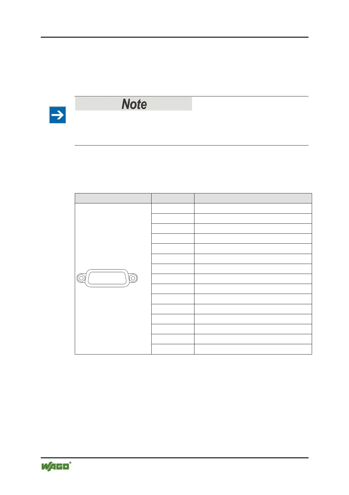
Table 15: Digital Inputs and Outputs: Pin Assignments
Connector Pin Description
1
DIN0+
2 DIN1+
3 DOUT0+
4 DOUT1+
5 Not assigned
6 Not assigned
7 Not assigned
8 Not assigned
9 DIN0-
10 DIN1-
11 DOUT0-
12 DOUT1-
13 Not assigned
14 Not assigned
1
2
3
4
15
5
6
8
9
7
10
11
12 13
14
15 Not assigned
Pos: 34.10 /Dokumenta tion allgemein/Glied erungselemente/---Seitenwechsel--- @ 3\mod_1221108045078_0.doc @ 21810 @ @ 1

 Loading...


