WAGO-I/O-SYSTEM 750 I/O Modules 245
758-874/000-131 WAGO-I/O-IPC-C6
Manual
Version 1.0.0
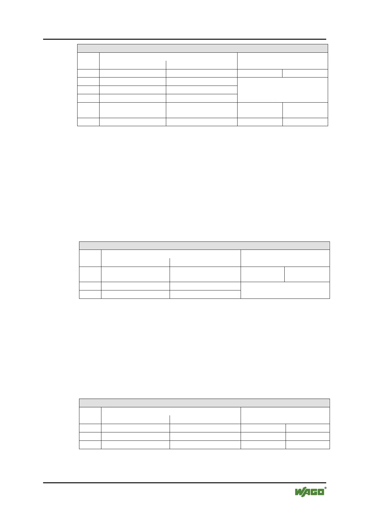
Output Process Image
Byte Destination
Offset
High Byte Low Byte
Description
0 reserved C0 reserved Control byte C0
1 D1 D0
2 D3 D2
3 D5 D4
Process data*) / Mailbox**)
4 C3 D6 Control byte C3
Process data*) /
reserved**)
5 C1 C2 Control byte C1 Control byte C2
*) Cyclic process image (Mailbox disabled)
**) Mailbox process image (Mailbox activated)
18.2.5.10 RTC Module
750-640
The RTC Module has a total of 6 bytes of user data in both the Input and Output
Process Image (4 bytes of module data and 1 byte of control/status and 1 byte ID
for command). The following table illustrates the Input and Output Process
Image, which have 3 words mapped into each image. Word alignment is applied.
Table 117: RTC Module 750-640
Input and Output Process Image
Byte Destination
Offset
High Byte Low Byte
Description
0 ID C/S Command byte
Control/status
byte
1 D1 D0
2 D3 D2
Data bytes
18.2.5.11 DALI/DSI Master Module
750-641
The DALI/DSI Master module has a total of 6 bytes of user data in both the Input
and Output Process Image (5 bytes of module data and 1 byte of control/status).
The following tables illustrate the Input and Output Process Image, which have 3
words mapped into each image. Word alignment is applied.
Table 118: DALI/DSI Master module 750-641
Input Process Image
Byte Destination
Offset
High Byte Low Byte
Description
0 D0 S DALI Response Status byte
1 D2 D1 Message 3 DALI Address
2 D4 D3 Message 1 Message 2

 Loading...


