WAGO-I/O-SYSTEM 750 Installing and Removing the I/O-IPC 47
758-874/000-131 WAGO-I/O-IPC-C6
Manual
Version 1.0.0
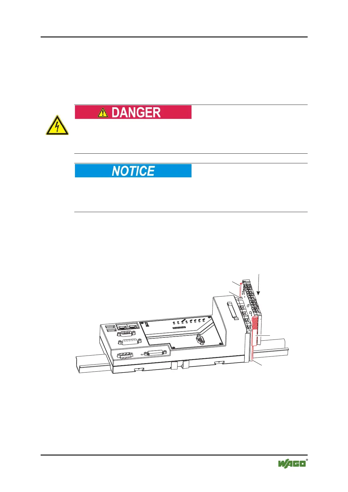
To connect the I/O modules, proceed as described below:
1. Disconnect from the power supply those parts of the system on which you
wish to mount the I/O-IPC.
2. Insert the slot (71) of each I/O module onto the key (70) of the previous
module.
Electric voltage!
When using 120/230V I/O modules, observe the safety precautions in the
accompanying manual. If these precautions are not observed, there is a danger of
electrical shock.
The highest current carrying capacity of the power contacts is 10A!
The maximum current carrying capacity of the I/O module power contacts must
not exceed 10 A. An increase in current can lead to overheating of the contacts
and damage to the I/O modules.
3. Connect the end module as the last.
When another I/O module is snapped on, the supply voltage for the sensors and
actuators is automatically conducted over the power jumper contacts. The
prerequisite is that the I/O modules used must also have power jumper contacts.
Pos: 36.15 /Serie 758 ( Funk, IPC und PFC)/Montieren/ Montage 758-87x FB - Bild 3 @ 10\ mod_1312439404391_21. doc @ 75846 @ @ 1
Figure 15: Connecting an I/O module to the I/O-IPC connecting clamp
Pos: 36.16 /Dokumenta tion allgemein/Glied erungselemente/---Seitenwechsel--- @ 3\mod_1221108045078_0.doc @ 21810 @ @ 1
70
70
71
71

 Loading...


