WAGO-I/O-SYSTEM 750 Connecting the Supply Voltage 53
758-874/000-131 WAGO-I/O-IPC-C6
Manual
Version 1.0.0
Table 20: Connections, contacts and supply module LEDs
Position LED/Operating Element Color/
Status
Meaning
60 Earth - Connection of protective earth
61 0 V DC - Ground (GND) of the supply voltage
62 Field supply, 24 V DC - 24V supply voltage for the sensors/actuators.
The power supply is protected against
reverse polarity.
For the supply of other field potentials; e. g.,
230 V AC, appropriate power supply
modules are available. You can find detailed
information on this in the manuals for the
power supply modules and in the 750-xxx
system description.
63 Power jumper contacts - Conduction of the field-side supply voltage
to the connected I/O modules.
64 Data contacts - These make the supply voltage (5 V, 1 A)
available for the electronics in the I/O
modules connected to the internal data bus.
The supply voltage is provided by the I/O-
IPC (connection X4).
44 LED Green/off The LED lights up if the field supply is
available (see Pos. 62). Otherwise, the LED
is off.
Requirements for connecting the power supply:
• You have connected two supply lines each to two voltage sources of
+24 V DC and 0 V DC in a de-energized state.
• You have connected the accompanying socket for the X4 connection to the
supply cable.
Pos: 38.4 /Dokumentatio n allgemein/Glieder ungselemente/---Seitenwechsel--- @ 3\mod_1221108045078_ 0.doc @ 21810 @ @ 1
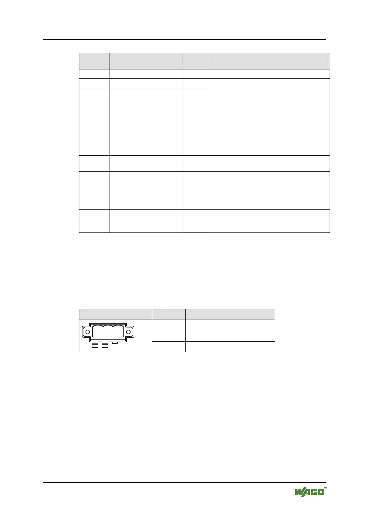
Table 21: Connection for Electronic Supply: Terminal Layout
X4 connector Pin Description
1
V_IN (+)
2 GND (-)
1
2
3
3 Shield (optional)

 Loading...


