244 I/O Modules WAGO-I/O-SYSTEM 750
758-874/000-131 WAGO-I/O-IPC-C6
Manual
Version 1.0.0
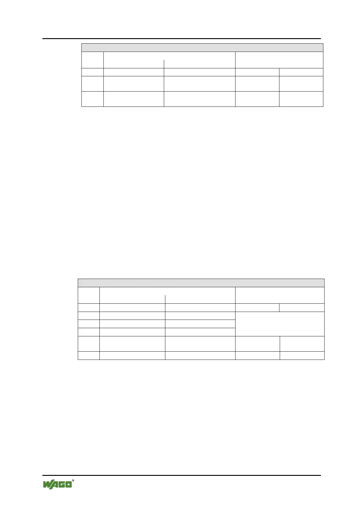
Output Process Image
Byte Destination
Offset
High Byte Low Byte
Description
0 C1 C0 Control byte C1 Control byte C0
1 D1 D0
Setpoint position
Setpoint position
(LSB)
2 D3 D2
Setpoint position
(MSB)
Setpoint position
18.2.5.9 Stepper Controller
750-670
The Stepper controller RS422 / 24 V / 20 mA 750-670 provides the fieldbus
coupler 12 bytes input and output process image via 1 logical channel. The data to
be sent and received are stored in up to 7 output bytes (D0 … D6) and 7 input
bytes (D0 … D6), depending on the operating mode.
Output byte D0 and input byte D0 are reserved and have no function assigned.
One I/O module control and status byte (C0, S0) and 3 application control and
status bytes (C1 ... C3, S1 ... S3) provide the control of the data flow.
Switching between the two process images is conducted through bit 5 in the
control byte (C0 (C0.5). Activation of the mailbox is acknowledged by bit 5 of the
status byte S0 (S0.5).
Table 116: Stepper Controller RS 422 / 24 V / 20 mA 750-670
Input Process Image
Byte Destination
Offset
High Byte Low Byte
Description
0 reserved S0 reserved Status byte S0
1 D1 D0
2 D3 D2
3 D5 D4
Process data*) / Mailbox**)
4 S3 D6
Status byte S3
Process data*) /
reserved**)
5 S1 S2 Status byte S1 Status byte S2
*) Cyclic process image (Mailbox disabled)
**) Mailbox process image (Mailbox activated)

 Loading...


