WAGO-I/O-SYSTEM 750 Description of I/O-IPC Interfaces 33
758-874/000-131 WAGO-I/O-IPC-C6
Manual
Version 1.0.0
Pos: 34.1 /Serie 758 ( Funk, IPC und PFC)/Besc hreibung der Schnittstel len/Beschreibung der S chnittstellen 758-87 x ETHERNET 1 @ 10\mod_131237 4986842_21.doc @ 75809 @ 12 @ 1
5 Description of I/O-IPC Interfaces
5.1 ETHERNET Interfaces (X8, X9)
Both ETHERNET interfaces of type RJ-45 are based on the 10/100 BASE-T
transmission standard. These enable, depending on the ETHERNET network used,
data exchange at a transmission rate of 10 Mbit/s or 100 Mbit/s in half-duplex and
full duplex operation respectively.
Pos: 34.2 /Serie 758 ( Funk, IPC und PFC)/Besc hreibung der Schnittstel len/Beschreibung der S chnittstellen 758-87 x - ETHERNET 2 @ 10\mod_131494 2425688_21.doc @ 78014 @ @ 1
The "ACT/LNK" and "Speed" LEDs of the two Ethernet interfaces indicate the
current operating status:
Table 12: ACT/LNK and Speed LED
LED Color/Status Cause
yellow Connection to a LAN available ACT/LNK
yellow flashing Data exchange is taking place.
off Transmission speed 10 Mbit/s Speed
green Transmission speed 100 Mbit/s
You have the following possibilities for connecting the I/O-IPC to a PC using
Ethernet:
• Directly, with the aid of a crossover cable
• Using a switch or hub in connection with a patch cable
The following table provides information on the Ethernet interface pin
assignments:
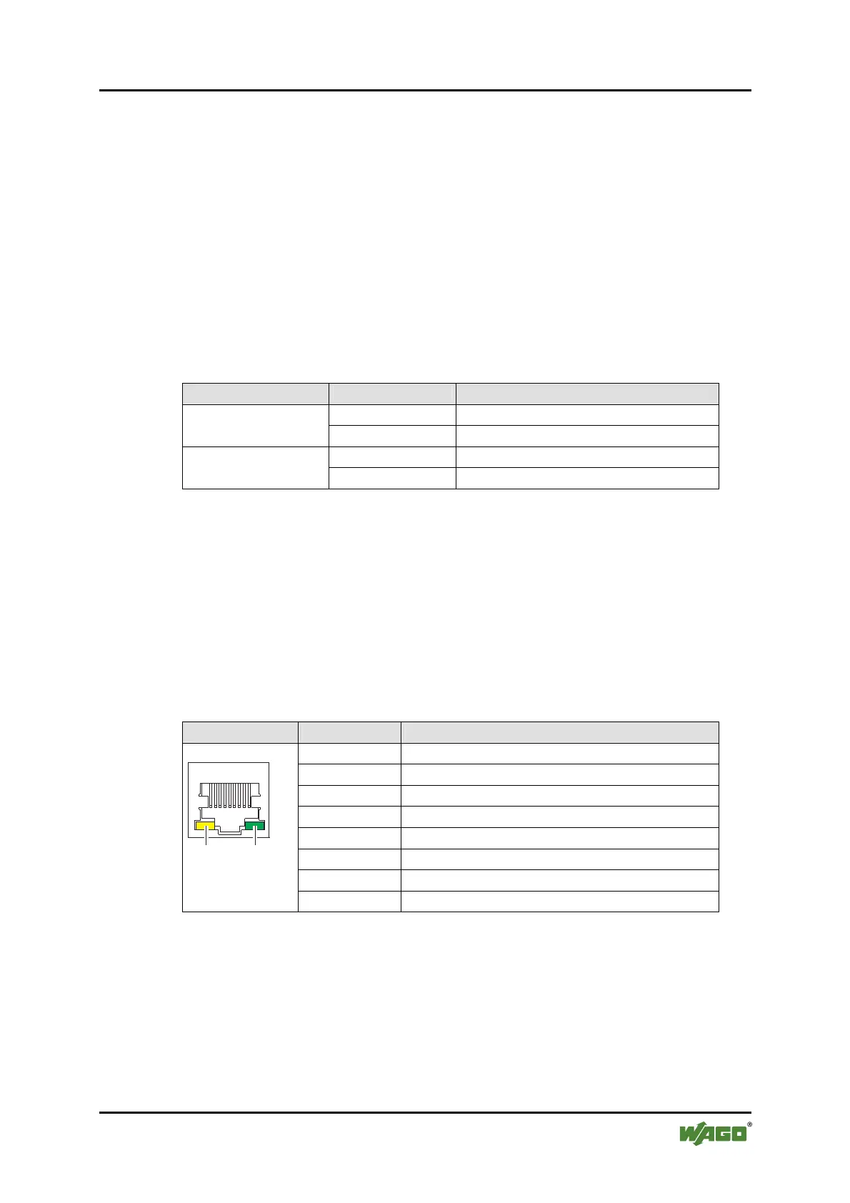
Table 13: ETHERNET Interfaces: Pin Assignments
Connector Pin Description
1 TD+
2 TD-
3 RD+
4 Not assigned
5 Not assigned
6 RD-
7 Not assigned
8
1
ACT/LNK
Speed
ACT LINK
Figure 6: RJ-45
Geode
8 Not assigned
Pos: 34.3 /Dokumentatio n allgemein/Glieder ungselemente/---Seitenwechsel--- @ 3\mod_1221108045078_0.doc @ 21810 @ @ 1

 Loading...


