Do you have a question about the WAGO WAGO-I/O-SYSTEM 752 and is the answer not in the manual?
Overview of manual content: technical details, setup, and operational guidance.
Covers copyright, personnel qualifications, and intended use of the product.
Defines the applicability and limitations of the manual's content.
Explains visual symbols used in the manual for warnings and notes.
Lists and defines technical acronyms used in the document.
Details the physical and functional aspects of the base module for wiring and connections.
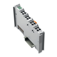
Describes the plug-in electronic module, its components, and diagnostics.
Covers network parameters like nodes, I/O points, segment length, and baud rates.
Details supply voltage, current, power, dimensions, housing, and fixing.
Covers input/output counts, ratings, protection, and conformity labelling.
Details operating conditions, mechanical strength, electrical safety, and EMC.
Covers mounting the base module onto the carrier rail and detaching it.
Details inserting/extracting the electronic module and using the marking label.
Explains how to set the node address using encoding switches on the electronic module.
Provides general guidelines for electrical installation, including ESD precautions and conductor connection.
Details the 24V DC supply connection and grounding requirements.
Explains how to connect 2-conductor and 3-conductor sensors to the input terminals.
Describes how to connect supply voltage for output groups, either internally or externally.
Explains how to connect actuators to the output terminals.
Details the D-SUB connector and specifications for PROFIBUS cabling.
Explains bus termination, connector types, and series inductance for PROFIBUS connection.
Provides recommendations for shielded cables, grounding, and avoiding spur lines for interference resistance.
Provides a visual representation of the module's internal electrical connections.
Explains the LED indicators for input voltage and value status.
Describes the LED indicators for output state, faults, and supply conditions.
Details the RUN and BF (Bus Failure) LEDs for PROFIBUS communication status.
Explains the 'OVERLOAD' LED and possible output faults it indicates.
Introduces PROFIBUS standards and the role of GSD files for module configuration.
Details where to obtain GSD and symbol files for configuration.
Explains the 12-byte parameter structure expected from the master, including watchdog settings.
Defines the identifier bytes for configuring inputs and outputs of the module.
Covers standard and device status diagnosis, including diagnostic headers and bits.
Explains how diagnostic bits DS1-DS4 relate to output groups.
Describes the organization of input and output data within the process image.
Mentions controller boards for communication and WAGO's PC interface board.
Discusses the need for configuration software and WAGO's NETCON software.
Lists optional accessories like GSD files, marking labels, fuses, and tools.
Provides definitions for key terms used in the manual.
| Product Category | I/O Systems |
|---|---|
| Manufacturer | WAGO |
| Input Voltage | 24 VDC |
| Protection Class | IP20 |
| Product Line | WAGO-I/O-SYSTEM |
| Number of Channels | Configurable, dependent on modules |
| Bus System | Ethernet |
| Power Supply | 24 V DC |
| Mounting Type | DIN rail |
| Modularity | Yes |
| Certifications | CE, UL |