Home
WAGO
I/O Systems
750
WAGO 750 - User Manual
90 pages
Manual
Specs
Ask a question
Save Page as PDF
To Next Page
To Next Page
Loading...
Manual
WAGO
-
I/O
-
SYSTEM 750
750
-
471
4AI U/I
Diff G
alv
4
-
Chann
el A
nalog Input
; for
Volta
ge/Cu
rrent
Version 1.0.0
2
Table of Contents
Main Page
Table of Contents
3
Notes about this Documentation
5
Validity of this Documentation
5
Copyrights
5
Copyright
7
Symbols
8
Number Notation
10
Font Conventions
10
Table 1: Number Notation
10
Table 2: Font Conventions
10
Important Notes
11
Legal Bases
11
Subject to Changes
11
Personnel Qualifications
11
Use of the WAGO-I/O-SYSTEM 750 in Compliance with Underlying Provisions
11
Technical Condition of Specified Devices
12
Disposal
12
Safety Advice (Precautions)
13
Device Description
15
Table 3: Compatibility List 750-471
16
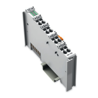
View
18
Figure 1: View
18
Table 4: Legend for Figure "View
18
Connectors
19
Data Contacts/Local Bus
19
Figure 2: Data Contacts
19
Power Jumper Contacts/Field Supply
20
Figure 3: Power Jumper Contacts
20
Table 5: Legend for Figure "Power Jumper Contacts
20
Cage Clamp
22
Figure 4: CAGE CLAMP ® Connectors
22
Table 6: Legend for Figure "CAGE CLAMP ® Connectors
22
Display Elements
23
Figure 5: Display Elements
23
Table 7: Legend for Figure "Display Elements
23
Schematic Diagram
25
Figure 6: Schematic Diagram
25
Figure 7: Circuit Diagram
25
Technical Data
26
Device Data
26
Supply
26
Isolation
26
Communication
26
Table 8: Technical Data - Device
26
Table 9: Technical Data - Supply
26
Table 10: Technical Data - Isolation
26
Table 11: Technical Data - Communication
26
Inputs
27
Connection Type
27
Table 12: Technical Data - Inputs
27
Table 13: Technical Data - Field Wiring
27
Table 14: Technical Data - Power Jumper Contacts
27
Table 15: Technical Data - Data Contacts
27
Climatic Environmental Conditions
28
Table 16: Technical Data - Climatic Environmental Conditions
28
Approvals
29
Standards and Guidelines
30
Process Image
31
Overview
31
Table 17: Process Image - I/O Module750-471
32
Status Bytes
33
Table 18: Status Byte CH1_S0
33
Process Data
34
Overview of Sensor Types
34
Table 19: Process Data, Signal Types
34
Table 20: Signal Types "0
35
Table 21: Signal Types "0
36
Signal Types "± 10 V", "± 200 MV" "± 20 Ma", Two's Complement (Default)
37
Table 22: Signal Types "± 10 V", "± 200 MV", "± 20 Ma", Two's Complement
37
Table 23: Signal Types "± 10 V", "± 200 MV" "± 20 Ma", Two's Complement with
38
Table 24: Signal Types "± 10 V", "± 200 MV" "± 20 Ma", Amount/Sign Format
38
Table 25: Signal Types "± 10 V", "± 200 MV" "± 20 Ma", Amount/Sign Format with
39
Signal Type "Namur NE43
40
Table 26: Signal Type "Namur NE43", Two's Complement
40
Table 27: Signal Type "Namur NE43", Two's Complement with Status Information
41
Table 28: Signal Type "Namur NE43", Amount/Sign Format
42
Table 29: Signal Type "Namur NE43", Amount/Sign Format with Status
43
Mounting
44
Mounting Sequence
44
Inserting and Removing Devices
45
Inserting the I/O Module
45
Figure 8: Insert I/O Module (Example)
45
Figure 9: Snap the I/O Module into Place (Example)
45
Removing the I/O Module
46
Figure 10: Removing the I/O Module (Example)
46
Connect Devices
47
Connecting a Conductor to the CAGE CLAMP
47
Figure 11: Connecting a Conductor to a CAGE CLAMP
47
Connection Examples
48
Figure 12: Connection Example 750-471
48
Commissioning
49
Parameterization with WAGO-I/O-CHECK
49
Figure 13: WAGO-I/O-CHECK User Interface
50
Parameterization Dialog
51
Figure 14: Parameterization Dialog 750-471
51
Toolbar on the Configuration Dialog
52
Figure 15: Toolbar
52
Table 30: Toolbar
52
Navigation Area
53
Figure 16: Navigation
53
Table 31: Navigation
53
Common
54
Figure 17: Parameter „Common
54
Table 32: "General" Parameters
54
Channel Settings
56
Figure 18: Parameter „Channel
56
Table 33: Parameter „Channel
56
Scaling
58
Figure 19: Parameter "Scaling
58
Table 34: "Scaling" Parameters
58
Calibration
60
Figure 20: "Calibration" Parameters
61
Table 35: Calibration Parameters
61
Figure 21: Offset Correction
62
Figure 22: Gain Correction
62
Scaling Measured Values
64
Table 36: Variable Legend - Scaling Measured Values
64
Diagnostics
65
I/O Module Behavior in the Event of an Error
65
Table 37: Priority Levels of Diagnostic Functions
65
Table 38: Behavior in the Event of an I/O Module Error Dependent on the
66
Firmware Changes
68
Use in Hazardous Environments
69
Marking Configuration Examples
70
Marking for Europe According to ATEX and Iecex
70
Figure 23: Marking Example According to ATEX and Iecex
70
Figure 24: Text Detail - Marking Example According to ATEX and Iecex
70
Table 39: Description of Marking Example According to ATEX and Iecex
71
Figure 25: Marking Example for Approved Ex I I/O Module According to ATEX
72
Figure 26: Text Detail - Marking Example for Approved Ex I I/O Module
72
Marking for America (NEC) and Canada (CEC)
73
Table 40: Description of Marking Example for Approved Ex I I/O Module According to ATEX and Iecex
73
Table 42: Description of Marking Example for Approved Ex I I/O Module
73
Figure 27: Marking Example According to NEC
74
Figure 28: Text Detail - Marking Example According to NEC 500
74
Table 41: Description of Marking Example According to NEC 500
74
Figure 29: Text Detail - Marking Example for Approved Ex I I/O Module
75
Figure 30: Text Detail - Marking Example for Approved Ex I I/O Module
75
Table 43: Description of Marking Example for Approved Ex I I/O Modules
75
Figure 31: Text Detail - Marking Example for Approved Ex I I/O Modules
76
Table 44: Description of Marking Example for Approved Ex I I/O Modules
76
Installation Regulations
77
Special Notes Regarding Explosion Protection
77
Special Notes Regarding ANSI/ISA Ex
79
Appendix
80
Configuration and Parameterization Using a GSD File with PROFIBUS DP and PROFINET IO
80
4AI U/I Diff/Galv Configuration
80
PROFIBUS DP Fieldbus Couplers/Controllers 750-333(/0Xx-000)
80
750-833(/0Xx-000)
80
PROFINET IO Fieldbus Couplers 750-375(/025-000), 750-377(/025-000)
80
Table 45: PROFIBUS DP Configuration
80
Table 46: Configuration 750-375(/025-000) und 750-377(/025-000)
80
4AI U/I Diff/Galv Parameterization
81
Figure 32: Example of the PROFIBUS DP Fieldbus Couplers/Controllers
81
Figure 33: Example of the Fieldbus Couplers/Controllers Parameterization Dialog
82
All PROFIBUS DP and PROFINET IO Fieldbus Couplers/Controllers
83
Table 47: Specific Module/Channel Parameters for 75X-461/003-000
83
PROFIBUS DP Fieldbus Couplers/Controllers 750-333(/0Xx-000), 750-833(/0Xx-000)
84
PROFINET IO Fieldbus Couplers 750-375(/025-000), 750-377(/025-000)
84
Table 48: General Module/Channel Parameters
84
Table 49: General Module/Channel Parameters
84
List of Figures
87
List of Tables
88
Need help?
Do you have a question about the WAGO 750 and is the answer not in the manual?
Ask a question
WAGO 750 Specifications
Print Specification
General
Power Supply
24 VDC
Category
I/O Systems
Series
750
Protection Class
IP20
Mounting
DIN rail mounting
Communication Protocol
PROFIBUS, CANopen, Modbus
Related product manuals
WAGO 752-323
36 pages
WAGO 750-881
74 pages
WAGO 750 XTR
108 pages
WAGO 750-338
192 pages
WAGO 750-530
50 pages
WAGO 750-842
334 pages
WAGO 750-841
242 pages
WAGO 750-461
28 pages
WAGO 750-306
152 pages
WAGO 752-823
36 pages
WAGO 750-830
360 pages
WAGO 750-882
450 pages