Do you have a question about the WAGO 750-842 and is the answer not in the manual?
Details the WAGO-I/O-SYSTEM components: fieldbus coupler/controller, I/O modules, and end module.
Covers safety notes (ESD) and mechanical installation procedures on a carrier rail.
Lists mechanical, environmental, and EMC specifications for the WAGO-I/O-SYSTEM 750.
Explains wire connection using CAGE CLAMP and carrier rail grounding requirements.
Details system and field-side power supply, 24V DC, 120V AC, 230V AC connections.
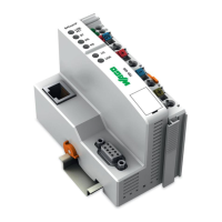
Covers description, hardware view, device supply, fieldbus connection, and display elements of the 750-342 coupler.
Explains process data exchange via MODBUS/TCP, master/slave principle, and memory areas.
Describes fault behavior for fieldbus failure and internal bus faults, including LED indications.
Details the hardware view, device supply, fieldbus connection, display elements, and configuration interface.
Details addressing the I/O modules and the address range for I/O module and fieldbus data.
Explains the operating system's startup process, PLC cycle, and fault handling.
Provides step-by-step procedures for starting up an ETHERNET TCP/IP fieldbus node and viewing HTML pages.
Describes the internal process image generation from I/O modules and data areas.
Explains the LED display for coupler operating status and node status, including blink codes.
Combines ETHERNET TCP/IP functions with PLC functionality for the 750-842 controller.
Explains data exchange via MODBUS/TCP, PLC functionality, and memory areas.
Details hardware view, device supply, fieldbus connection, display elements, and configuration interface.
Details addressing I/O modules and the address range for I/O module and fieldbus data.
Explains controller startup, PLC cycle, and operating modes (RUN/STOP).
Provides procedures for starting up an ETHERNET TCP/IP fieldbus node and viewing HTML pages.
Describes programming the PFC using WAGO-I/O-PRO 32, including ETHERNET library elements.
Describes fault behavior for fieldbus failure and internal bus faults, including LED indications.
Lists and reviews analog output modules for DC 0-10V and DC ±10V signals.
Lists and reviews various 2-channel and 4-channel digital input modules with their specifications.
Lists and reviews various digital output modules, including standard, relay, and solid-state types.
Lists and reviews analog input modules for current, voltage, resistance, and thermocouple sensors.
Explains ETHERNET principles, network architecture, transmission media, and topologies like star and tree.
Covers MODBUS/TCP, Bootstrap Protocol (BootP), and HyperText Transfer Protocol (HTTP).
Details channel access method (CSMA/CD) and communication protocols like IP, TCP, UDP.
Shows how MODBUS functions access process image data, distinguishing between register and coil functions.
Details MODBUS function codes (FC1-FC23), their requests, responses, and exception codes.
Details the watchdog function for monitoring data transfer and handling fieldbus failures.
Provides insight into using WAGO ETHERNET fieldbus coupler/controller with SCADA software for visualization.
| Brand | WAGO |
|---|---|
| Model | 750-842 |
| Category | I/O Systems |
| Language | English |