WAGO-I/O-SYSTEM 750 I/O Modules 229
758-874/000-131 WAGO-I/O-IPC-C6
Manual
Version 1.0.0
18.2.2 Digital Output Modules
Digital output modules use one bit of data per channel to control the output of the
corresponding channel. These bits are mapped into the Output Process Image.
Some digital modules have an additional diagnostic bit per channel in the Input
Process Image. The diagnostic bit is used for detecting faults that occur (e.g., wire
breaks and/or short circuits). For modules with diagnostic bit is set, also the data
bits have to be evaluated.
When analog output modules are also present in the node, the digital image data is
always appended after the analog data in the Output Process Image, grouped into
bytes.
18.2.2.1 1 Channel Digital Output Module with Input Process Data
750-523
The digital output modules deliver 1 bit via a process value Bit in the output
process image, which is illustrated in the input process image. This status image
shows "manual mode".
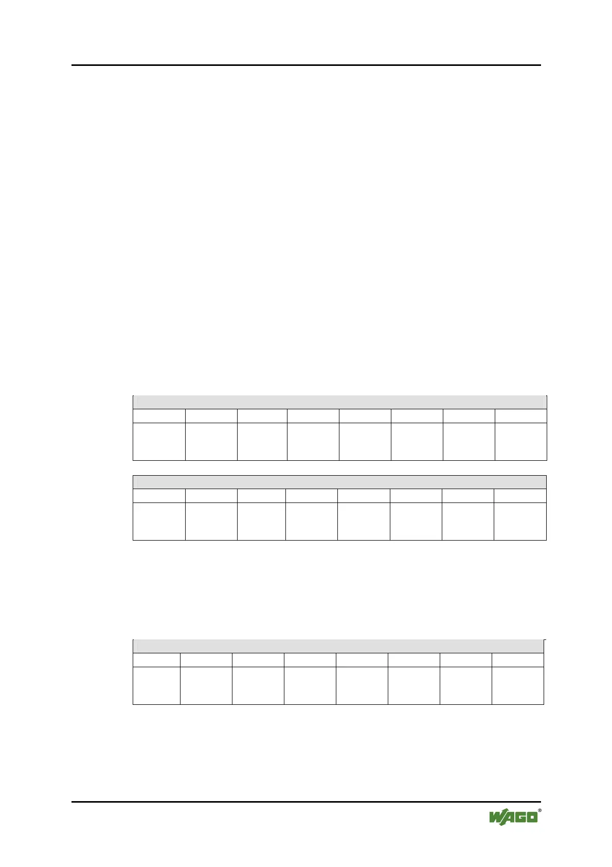
Table 88: 1 Channel Digital Output Module with Input Process Data
Input Process Image
Bit 7 Bit 6 Bit 5 Bit 4 Bit 3 Bit 2 Bit 1 Bit 0
not used
Status bit
“Manual
Operation“
Output Process Image
Bit 7 Bit 6 Bit 5 Bit 4 Bit 3 Bit 2 Bit 1 Bit 0
not used
controls
DO 1
Channel 1
18.2.2.2 2 Channel Digital Output Modules
750-501, -502, -509, -512, -513, -514, -517, -535, (and all variations),
753-501, -502, -509, -512, -513, -514, -517
Table 89: 2 Channel Digital Output Modules
Output Process Image
Bit 7 Bit 6 Bit 5 Bit 4 Bit 3 Bit 2 Bit 1 Bit 0
controls
DO 2
Channel 2
controls
DO 1
Channel 1

 Loading...


