Do you have a question about the WAGO 750-559 and is the answer not in the manual?
Covers copyright, personnel qualification, and intended use of the product.
Explains the meaning of graphical symbols like danger, warning, attention, and ESD.
Details decimal, hexadecimal, and binary number formats used in the manual.
Provides crucial safety instructions for handling and operating the modules.
Defines the manual's coverage of the 750-559 module and its relation to the Fieldbus Coupler.
Overview of analog output modules within the WAGO-I/O-SYSTEM 750.
Details the 4 AO DC 0-10 V module, its variations, and features.
Lists different item numbers and designations for the 750-559 module.
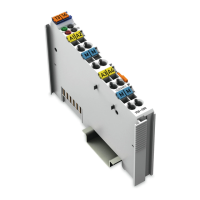
Illustrates the module's physical layout and connection terminals.
Explains the functionality, signal transmission, LEDs, and power supply of the module.
Describes the function and state of the module's indicator LEDs.
Provides the internal circuit diagram for the 750-559 module.
Lists detailed specifications, standards, and approvals for the module.
Explains how module data is transmitted via the process image.
Details the numerical scaling for output values in the standard process image.
| Series | 750 |
|---|---|
| Input Channels | 8 |
| Input Type | Digital |
| Voltage Range | 24 V DC |
| Width | 12 mm |
| Supply Voltage | 24 V DC |
| Configuration | Plug-in |