WAGO-I/O-SYSTEM 750 I/O Modules 143
750-306 DeviceNet
TM
Fieldbus Coupler
Manual
Version 2.0.0
Stepper module
750-670
750-671
750-672
750-673
The stepper module makes a 12-byte input/output process image available.
The data to be sent and received is stored in up to 7 input/output bytes depending
on the operating mode. If the mailbox is activated, the first 6 data bytes are
overlaid with mailbox data.
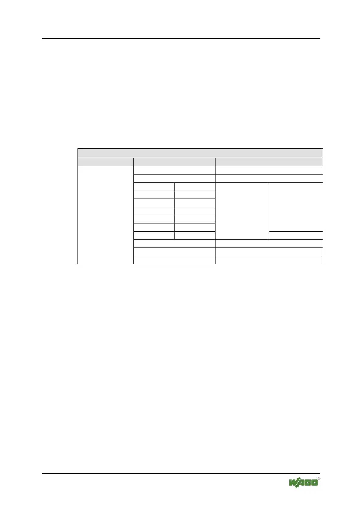
Table 147: Input/Output Process Image, Stepper Module
Input/Output Process Image
n
Data bytes
Mailbox bytes
(mailbox activated)
Status byte (mode specific)
Status byte (mode specific)
Status byte (mode specific)
These specialty modules represent 1 x 12 bytes and occupy 1 instance in class
(0x67) and 1 instance in class (0x68).


 To Next Page