Do you have a question about the Walchem W600 Series and is the answer not in the manual?
Details sensor measurement capabilities, ranges, resolutions, and accuracy.
Electrical specifications for inputs, outputs, and power.
Covers enclosure, dimensions, and sensor mechanical specifications.
Lists configurable parameters and their operational limits.
Instructions for inspecting the controller and its components upon arrival.
Guidelines for physically mounting the controller enclosure to a wall.
Instructions for installing the immersible copper sensor in a tank.
Guidance for installing flow-through copper sensors and associated sample loops.
Guidance for installing flow-through nickel sensors and associated sample loops.
General guidance for installing various other types of sensors.
Explains the meaning of various symbols used on the controller interface.
Details wiring procedures and safety precautions for electrical connections.
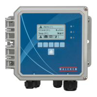
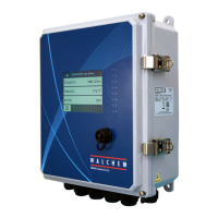
Describes the physical front panel layout and components of the controller.
Explains how to navigate and interact with the controller's touchscreen interface.
Details the meaning and usage of various icons displayed on the controller.
Outlines the procedure for initial setup and configuration of inputs.
Provides instructions on how to safely power down the controller.
Describes how to view and manage active alarms on the controller.
Explains how to access and configure sensor and digital inputs.
Guides users through configuring relay and analog outputs for control modes.
Covers global settings, security, network, and file management options.
Steps for connecting the controller to a local area network.
Instructions for establishing a direct network connection to a PC.
How to use a web browser to access and control the controller.
Procedures for cleaning copper and nickel sensors for accurate readings.
Guidelines for maintaining pH electrodes, including cleaning and calibration frequency.
Instructions on safely replacing fuses for powered relays in the controller.
Addresses common reasons and solutions for calibration failures across sensors.
Explains alarm messages, their causes, and corrective actions.
Steps to evaluate and troubleshoot conductivity electrodes.
Steps to evaluate and troubleshoot pH/ORP electrodes.
Interprets status of diagnostic lights on controller circuit boards.
| Display | LCD |
|---|---|
| Input Voltage | 100-240V AC, 50/60Hz |
| Output Type | Relay |
| Communication | Modbus RTU |
| Storage Temperature | -20 to 70°C (-4 to 158°F) |
| Humidity | 5% to 95% non-condensing |
| Enclosure Rating | NEMA 4X/IP65 |
| Outputs | Relay |
| pH Range | 0 to 14 pH |