EasyManua.ls Logo

Walchem WCT400 Series - User Manual

Default Icon
43 pages
Print Icon
To Next Page IconTo Next Page
Loading...
WCT400/410 Series
Cooling Tower Conductivity Controller
Instruction Manual
Five Boynton Road Hopping Brook Park Holliston, MA 01746 USA
TEL: 508-429-1110 FAX: 508-429-7433 WEB: www.walchem.com
W
CT400/410 Controllers
W A L C H E M
IWAKI America Inc.

Questions and Answers

  • A
    angelsmithJul 30, 2025
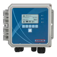
    What to do if my Walchem WCT400 Controller shows a HIGH ALARM?
    • H
      hayeshaileyJul 30, 2025
      If the Walchem Controller displays a HIGH ALARM, several factors could be responsible. It may be due to a dirty or faulty electrode, which may require cleaning or evaluation. The solenoid valve might be faulty and need repair or replacement. Improper wiring of the valve or controller could be the cause, requiring wiring correction. If conductivity rose over the alarm limit during biocide lockout, allow normal bleed to occur. A clogged Y-strainer in the bleed line should be cleaned. Lastly, a faulty bleed relay might need replacement.
  • T
    Thomas McdonaldAug 3, 2025
    What to do if my Walchem WCT400 displays a LOW ALARM?
    • G
      Gregory MooreAug 3, 2025
      If the Walchem Controller shows a LOW ALARM, it could be due to several reasons. First, check if the sensor is disconnected and reconnect it, also check the cable for continuity. If the sensor is dry, inspect the tee for obstructions, verify flow, or change the electrode location. Check the pre-bleed setting compared to the % low, as it might be set too low. A solenoid valve stuck open needs repair or replacement. Evaluate the electrode and replace if necessary. Ensure proper wiring of the electrode. Lastly, a faulty bleed relay might need replacement.
  • E
    Elizabeth CoxAug 7, 2025
    What to do if my Walchem WCT400 is showing a SENSOR ERROR?
    • M
      Mitchell JohnsonAug 7, 2025
      If your Walchem Controller displays a SENSOR ERROR, it could be due to a few reasons. A short in the back or red electrode wire requires disconnection. A faulty electrode should be replaced. A faulty controller can be verified via a failed self-test.
  • Q
    qhendersonAug 12, 2025
    What to do if my Walchem WCT400 displays a BLEED TIMEOUT?
    • S
      Sarah CoxAug 12, 2025
      If your Walchem Controller shows a BLEED TIMEOUT error, the programmed value might be too low for normal conditions, so increase the Bleed Time Limit. The bleed flow rate might be too low, so check for a clogged strainer or insufficient pressure differential. Also, the bleed valve might not be opening, so check for a faulty bleed valve, bleed valve wiring, or the controller relay.
  • N
    Nancy SmithAug 16, 2025
    Why the conductivity readout does not change on my Walchem Controller?
    • R
      Roger FinleyAug 16, 2025
      If your Walchem Controller's conductivity readout isn't changing, first, check for flow through the system, as the electrode may be dry. Verify the wiring to the electrode. If the readout changes to 900-1100 during a self-test, the problem lies with the electrode or its connections. If it remains at zero, the issue is with the controller. The electrode might be dirty or faulty, requiring evaluation. Also, ensure the sample isn't stagnant by checking the system for proper flow.
  • O
    opattonAug 20, 2025
    What to do if my Walchem WCT400 displays NO FLOW?
    • J
      Jacob MendezAug 20, 2025
      If your Walchem Controller displays a NO FLOW error, check the recirculating pump, valves, etc. Also, check the flow switch/cable for an open circuit. Disconnect the flow switch and short the input with a piece of wire; if the "no flow" message disappears, the switch or cable may be faulty. Make sure there is sufficient pressure drop through the sample stream and check the piping.
  • T
    Thomas HaleAug 25, 2025
    What to do if my Walchem WCT400 displays a TEMP ERROR?
    • Z
      zhughesAug 25, 2025
      If the Walchem Controller displays a TEMP ERROR, it might be due to a disconnected green or white electrode wire, which needs to be reconnected. Alternatively, the electrode could be faulty and require replacement. You can revert to manual temperature compensation by cycling the power off and on.

Summary

Statement of Limited Warranty

Introduction to Walchem WCT400;410 Controllers

Walchem WCT400;410 Specifications

Measurement Performance Specifications

Details conductivity and temperature accuracy, resolution, and range.

Electrical Input and Output Specifications

Covers input power, input signals, outputs, and agency approvals.

Mechanical Specifications

Details enclosure material, dimensions, display, and temperature limits.

WCT Controller Variables and Limits

Lists operational parameters and their acceptable ranges for various menus.

Unpacking and Installation Guide

Unit Unpacking Procedure

Instructions for inspecting the controller carton and its contents upon arrival.

Mounting the Electronic Enclosure

Guidelines for wall mounting the controller unit securely and considering clearances.

System Installation Guidelines

Advice on placing the electrode, routing cables, and connecting plumbing parts.

Electrical Icon Definitions

Explains the meaning of standard electrical symbols used in diagrams.

Electrical Installation Procedures

Electrical Installation Safety Precautions

Important warnings regarding live circuits, panel opening, and grounding.

Wiring and Installation Best Practices

Guidance on power cord usage, access to disconnects, trained personnel, and grounding.

Controller Function Overview

Front Panel Controls and Indicators

Describes the buttons, display, and LEDs on the controller's front panel.

Summary Display Screen

Explains the bar graph, conductivity readings, and status indicators shown.

Keypad Navigation and Operation

Details how to use the directional and function keys for menu navigation and value changes.

Access Code Security Feature

Explains enabling and using the access code for parameter protection.

Controller Startup Procedures

Steps for initial and normal startup, including calibration and parameter setup.

Controller Shut Down Procedure

Instructions on how to safely turn off the controller.

Controller Operation and Menus

Main Menu Navigation

Explains how to access and navigate the main menu structure and its items.

Conductivity Menu Settings

Conductivity Calibration Procedure

Steps to calibrate the conductivity sensor using a meter or buffer solution.

Conductivity Sensor Self Test

How to run a self-test to verify sensor and controller functionality.

Conductivity Unit Selection

How to choose between µS/cm and ppm units for conductivity display.

PPM Conversion Factor Setting

Setting the conversion factor for ppm readings.

Conductivity Sampling Mode Setup

Configuring continuous or intermittent sampling modes for conductivity measurement.

Intermittent Sample Interval Setting

Setting the time between conductivity samples for intermittent mode.

Intermittent Sample Duration Setting

Setting the length of each conductivity sample for intermittent mode.

Raw Conductivity Reading Display

Displays the temperature-compensated conductivity before calibration.

Temperature Menu Settings

Temperature Calibration Procedure

Steps to calibrate the temperature reading using a thermometer.

Manual Temperature Setting

Manual adjustment of temperature when sensor is not detected.

Temperature Unit Selection

Choosing between Celsius (°C) and Fahrenheit (°F) for temperature display.

Temperature Compensation Mode

Selecting between manual and automatic temperature compensation.

Bleed Menu Configuration

Bleed Set Point Configuration

Setting the conductivity value to trigger the bleed output ON.

Bleed Dead Band Configuration

Setting the conductivity range to turn the bleed output OFF.

Bleed Time Limit Setting

Setting a maximum duration for the bleed output to remain active.

Bleed Reset Timer Function

Resets the bleed timer after it has been exceeded.

Bleed Volume Configuration

Setting the volume of water to bleed in specific modes.

Makeup Volume Configuration

Setting makeup water volume to trigger bleed in specific modes.

Bleed Mode Selection

Choosing between High Set Point, Low Set Point, or Volume modes.

Bleed Hand;Off;Auto Mode

Selecting manual, off, or automatic operating modes for the bleed output.

Feed Menu Configuration

Bleed and Feed Mode Settings

Synchronizing feed output with bleed output, including lockout.

Feed % of Bleed Mode Setup

Feed duration based on a percentage of bleed time.

Feed % of Time Mode Setup

Feed duration based on a percentage of a timed cycle.

Feed Based on Water Contactor Input

Feed triggered by pulses from a water contactor.

Feed Based on Paddlewheel Input

Feed triggered by volume detected by a paddlewheel sensor.

Chemical Feed Mode Selection

Selecting the overall chemical feed mode.

Feed Hand;Off;Auto Mode

Selecting manual, off, or automatic operating modes for the feed output.

Water Meter (WM1;WM2) Setup

Water Meter Total Reset

Resets the totalizer display for the water meter.

Water Meter Volume per Contact

Setting the volume of makeup per contact for water contactor input.

Paddlewheel K Factor Setting

Entering pulses per unit volume for paddlewheel sensors.

Water Meter Total Units Selection

Choosing units (Gallons or Liters) for the totalizer.

Water Meter Type Configuration

Selecting the type of water meter input (Contactor, Paddlewheel, Not Used).

Biocide (Bio1;Bio2) Menus

Program Biocide Adds

Scheduling specific biocide addition times and durations.

Biocide Pre-Bleed Configuration

Setting conductivity set points for pre-bleed before biocide addition.

Biocide Lockout Time Setting

Setting lockout duration after a biocide add cycle.

Biocide Add Mode Selection

Choosing the cycle type (daily, 1, 2, 4 weeks) for biocide additions.

Biocide Hand;Off;Auto Mode

Selecting manual, off, or automatic operating modes for biocide output.

Time Setting for Biocide;Datalog

Setting Controller Time and Date

Adjusting the internal clock for biocide adds and datalogging.

Conductivity Alarm Configuration

Low Conductivity Alarm Threshold

Setting the percentage below set point for low conductivity alarm activation.

High Conductivity Alarm Threshold

Setting the percentage above set point for high conductivity alarm activation.

4-20 mA Output Configuration

4 mA Output Set Point

Conductivity value corresponding to 4mA output.

20 mA Output Set Point

Conductivity value corresponding to 20mA output.

4-20 mA Output Calibration

Calibrating fixed 4mA and 20mA outputs for connected equipment.

Access Code Security Settings

Enabling Access Code Feature

Activating or deactivating the access code security.

Customizing Access Code Value

Setting a new four-digit access code.

Datalogging and Data Export

Datalogging Features Overview

Description of Current, Backup, Event, and Reset logs and their data.

Exporting Datalog and Event Logs

Procedures for downloading datalogs and event logs via USB.

Exporting Reset Log Data

Procedure for downloading the reset log to a USB flash drive.

Configuration File Management

Exporting Controller Configuration

Saving controller set points to a USB flash drive as a UCF.ini file.

Importing Controller Configuration

Loading configuration settings from a USB flash drive into the controller.

Software Upgrade Procedure

Performing Software Upgrade

Steps to upgrade controller software using a USB flash drive.

Controller Maintenance

Conductivity Electrode Cleaning

Procedures and frequency for cleaning the conductivity electrode.

Fuse Replacement Procedure

Controller Troubleshooting Guide

Understanding Error Messages

Explains common error messages and their possible causes and corrections.

Troubleshooting Conductivity Readout Issues

Guides for diagnosing conductivity readings stuck at zero or other values.

Evaluating Conductivity Electrode Performance

Steps to diagnose issues with the conductivity electrode or controller.

Walchem Service Policy and Warranty

Walchem WCT400 Series Specifications

General IconGeneral
BrandWalchem
ModelWCT400 Series
CategoryController
LanguageEnglish

Related product manuals