Step 7
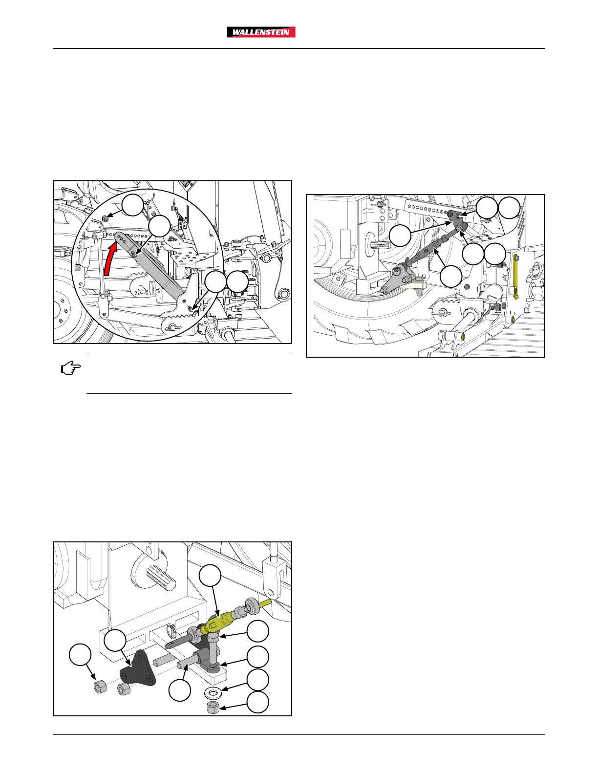
Once the backhoe is straight and level and the Center Link and
Side Tieback Bars are aligned, loosely bolt them together with
3042W103 RH Backhoe Strut (item 10) and 3042W104 LH
backhoe Strut (item 11) using Z71745 3/4"NC x 4-1/2" hex head
bolts (item 22) and Z72271 3/4" hex locknuts (item 24).
Bolt the opposite end of the struts to the backhoe brackets with
Z71720 3/4"NC x 2" hex head bolts (item 20) and Z72271 3/4"
hex locknuts (item 24).
24
24
22
20
If a PTO Hydraulic Power Pack is being used
with the backhoe, the drawbar brace cannot be
installed. Skip Steps 8–10.
Step 8
Assemble two 3041L214 Lower Linkage Plates (item 2) to the
tractor's draw bar as shown. Use three 71745 3/4"NC x 4-1/2"
hex head bolts (item 22) and Z72271 3/4" hex locknuts (item
24). Assemble with 3042W105 Drawbar Tab (item 12).
Fasten Drawbar Tab (item 12) to the tractor's swinging drawbar
with Z71730 3/4"NC x 3" hex head bolt (item 21), 3042L2108
Drawbar Washer (item 4), and Z72271 3/4" hex locknuts (item
24).
24
22
2
15
21
12
24
4
Step 9
Assemble 3041L213 Upper Linkage Plates (item 1) to the tie
back assembly as shown below. Use two 71745 3/4"NC x
4-1/2" hex head bolts (item 22) and Z72271 3/4" hex locknuts
(item 24).
Step 10
Attach Z11501 Toplink (item 15) to the upper linkage plates
with Z71640 5/8"NC x 4" hex head bolt (item 19) and Z72261
5/8"NC hex locknut (item 23).
15
1
19
22
23
24
Step 11
Check once more that your backhoe is straight and level. Adjust
if required and snug up the turnbuckle.
Step 12
Tighten up all the bolts to finalize the assembly.
Step 13
Check backhoe functions:
• start the tractor
• lower the stabilizers
• check all functions of the backhoe
• double-check all fasteners and three-point hitch is
solidly attached and secure
6
PT322