Assembly Instructions - Spray Valve SMS-02
Walther Systemtechnik GmbH – D 76726 Germersheim
Telefon: +49 (0)7274-7022-0 Telefax: +49 (0)7274-7022-91
http://www.walther-2000.de – info@walther-2000.de
Assembly Instructions
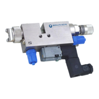
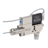
Spray Valve SMS-02
Article Number: S02-….
Picture: Spray Valve SMS-02 with flat air cap and raster-needle lock
NOTE
Please read the Assembly Instructions carefully before first using the incomplete device and
strictly adhere to the instructions!
The incomplete device may only be worked with and worked on by persons who are familiar
with the assembly instructions and the current regulations for industrial safety and accident
prevention.
Always keep this translated version of the “Original Assembly Instructions“ at the incomplete
device! The instructions have to be available anytime!