2
03.11
-
-
-
-
TOR.119.--.M.4L Rev. A1
VAR
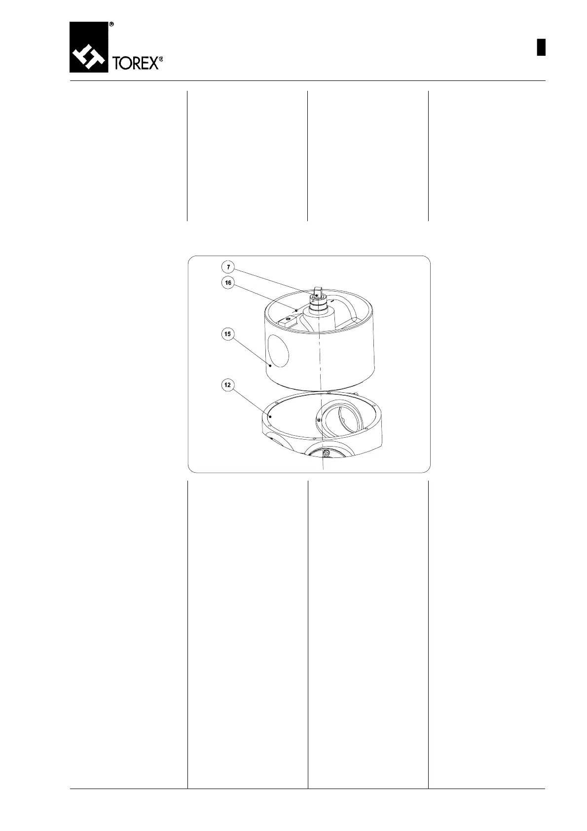
Per smontare il perno comando
(pos. 7, fig.14) procedere nel
seguente modo:
1) Una volta tolto il coperchio del
deviatore (pos. 3, fig.12)
come da istruzioni sopraripor-
tate, si può accedere alla vite
(pos. 16, fig.14) posta sul
mozzo del tamburo (pos. 15,
fig.14).
2) Svitare la vite (pos. 16, fig.
14) dal mozzo del tamburo.
3) A questo punto il perno co-
mando (pos. 7,fig.14) si può
sfilare dal tamburo.
N.B.: Per rimontare i particolari
seguire il procedimento descrit-
to nel paragrafo “MONTAGGIO
DEL COPERCHIO E DEL TAMBU-
RO”, avendo cura di pulire accu-
ratamente la parte interna del
corpo, e di non danneggiare le
tenute gonfiabili.
N.B.: il non attenersi strettamen-
te alle suddette istruzioni può
causare dei problemi ed invali-
dare la garanzia sulle macchine
fornite.
DRIVE PIN DISASSEMBLY - AUSBAU DES STEUERBOLZENS
DEMONTAGE DE L’AXE DE COMMANDE - SMONTAGGIO DEL PERNO COMANDO
Fig. 14
5) Afferrare saldamente il tam-
buro interno (pos. 15, fig.14),
ed estrarlo dalla parte aperta
del corpo deviatore (pos. 12,
fig.14).
6) Per le taglie maggiori, riavvi-
tare la ghiera (pos. 8, fig.13)
alla parte filettata del tambu-
ro (pos. 15, fig.14), ed usarla
come aggancio per il solleva-
mento ed estrazione dal cor-
po (pos. 12, fig.14) facendo
attenzione a non danneggiar-
lo.
33
MAINTENANCE- DIVERTER VALVE DISASSEMBLY
WARTUNG – AUSBAU DER ROHRWEICHE
ENTRETIEN – DEMONTAGE VANNE DEVIATRICE
MANUTENZIONE - SMONTAGGIO DEVIATORE
5) Hold the internal drum (pos.
15, Fig.14) firmly and remove
it through the open part of the
diverter valve body (pos. 12,
Fig.14).
6) For larger sizes, refit the ring
nut (pos. 8, Fig.13) to the
threaded part of the drum
(pos. 15, Fig.14), and use it
as a hook for lifting and re-
moving it from the body (pos.
12, Fig.14) taking care to
avoid damaging it.
5) Die Innentrommel (Pos. 15,
Abb.14) energisch festhalten
und aus dem offenen Teil des
Weichengehäuses (Pos. 12,
Abb. 14) herausziehen.
6) Bei den größeren Baugrößen
die Ringmutter (Pos. 8, Abb.
13) wieder am Gewindeteil
der Trommel (Pos. 15, Abb.
14) anschrauben und als Hil-
fe zum Heben und Heraus-
ziehen aus dem Gehäuse
(Pos. 12, Abb. 14) benutzen,
wobei zu beachten ist, dass
nichts beschädigt wird.
5) Saisir solidement le tambour
interne (pos. 15, fig.14), et
l’extraire par le côté ouvert
dub corps déviateur (pos.
12, fig.14).
6) Pour les faille plus grandes,
revisser la bague (pos. 8,
fig.13) à la partie filetée du
tambour (pos. 15, fig.14), et
l’utiliser comme crochet pour
soulever et extraire le corps
(pos. 12, fig.14) en faisant
attention à ne pas l’endom-
mager.
Um den Steuerbolzen (Pos. 7,
Abb. 14) auszubauen, geht man
wie folgt vor:
1) Nach dem Ausbau des Wei-
chendeckels (Pos. 3, Abb.12)
gemäß den oben stehenden
Anleitungen erhält man Zu-
griff zu der Schraube (Pos.
16, Abb.14), die sich auf der
Trommelnabe (Pos. 15,
Abb.14) befindet.
2) Die Schraube (Pos. 16, Abb.
14) von der Trommelnabe
losschrauben.
3) Nun kann man den Steuerbol-
zen (Pos. 7, Abb. 14) aus der
Trommel herausziehen.
Anm.: Um die Einzelteile wieder
einzubauen, das Verfahren be-
folgen, das im Abschnitt „EINBAU
DES DECKELS UND DER TROM-
MEL” beschrieben ist. Dabei den
Innenteil des Gehäuses sorgfäl-
tig reinigen und darauf achten,
das man die aufblasbaren Dich-
tungen nicht beschädigt.
Anm.: Wenn die folgenden An-
weisungen nicht genau beach-
tet werden, kann es zu Problem
kommen und die auf die geliefer-
ten Maschinen eingeräumte Ga-
rantie kann verfallen.
To remove the drive pin (pos. 7,
Fig.14) proceed as follows:
1) After removing the diverter
valve cover (pos. 3, Fig.12)
according to the instructions
given above, the screw (pos.
16, Fig.14) on the drum hub
(pos. 15, Fig.14) can be ac-
cessed.
2) Unscrew the screw (pos. 16,
Fig. 14) from the drum hub.
3) The drive pin (pos. 7, Fig.14)
can now be removed from
the drum.
NOTE: To reassemble the parts,
follow the procedure described
in the “COVER AND DRUM AS-
SEMBLY” paragraph, cleaning
the inside of the body carefully,
and taking care to avoid damag-
ing the inflatable seals.
NOTE: failure to follow the above
instructions can cause problems
and lead to invalidation of the
warrantee on the machines sup-
plied.
Pour démonter l’axe de comman-
de (pos. 7, fig.14) procéder de
la manière suivante :
1) Une fois le couvercle de la
vanne déviatrice enlevé
(pos. 3, fig.12) en suivant les
instructions ci-dessus, on
peut accéder à la vis (pos.
16, fig.14) placé sur le moyeu
du tambour (pos. 15, fig.14).
2) Dévisser la vis (pos. 16, fig.
14) du moyeu du tambour.
3) On peut alors retirer l’axe de
commande (pos. 7,fig.14) du
tambour.
N.B.: Pour remonter les pièces
suivre la procédure décrite dans
le paragraphe “MONTAGE DU
COUVERCLE ET DU TAMBOUR”,
en prenant soin de nettoyer à
fond la partie interne du corps et
de ne pas endommager les joints
gonflables.
N.B.: Le non respect des instruc-
tions suivantes peut être à l’ori-
gine de problèmes et invalider la
garantie sur les machines four-
nies.
 Loading...