2
03.11
-
-
-
-
TOR.119.--.M.4L Rev. A1
VAR
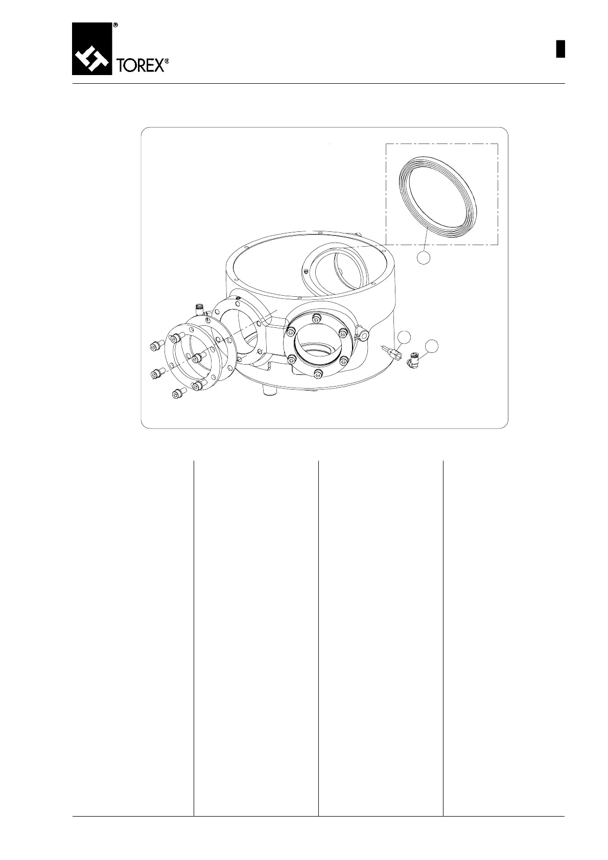
INFLATABLE SEALS DISASSEMBLY - AUSBAU DER AUFBLASBAREN DICHTUNGEN
DEMONTAGE DES JOINTS GONFLABLES - SMONTAGGIO DELLE TENUTE GONFIABILI
Fig. 16
20
19
17
1) Après avoir enlevé le tambour
interne (pos. 15, fig. 14) du
corps de la vanne déviatrice
(pos. 12, fig. 14), comme dé-
crit précédemment, on peut
accéder aux joints gonflables
(pos. 17, fig. 16).
2) Les joints gonflables (pos. 17,
fig. 16) sont introduits à l’in-
térieur d’un logement prévu
dans le corps de la vanne
déviatrice au niveau des deux
bouches de sortie et de la
bouche d’entrée.
3) Les extraire en faisant atten-
tion à ne pas les endomma-
ger surtout dans la partie d’in-
jection de l’air (pos. 19, fig.
16 – et photo Fig. 17).
1) Nach dem Ausbau der Innen-
trommel (Pos. 15, Abb. 14)
aus dem Weichengehäuse
(Pos. 12, Abb. 14), wie wei-
ter oben beschrieben wurde,
hat man nun Zugriff zu den
aufblasbaren Dichtungen
(Pos. 17, Abb. 16).
2) Die aufblasbaren Dichtungen
(Pos. 17, Abb. 16) befinden
sich innerhalb einer Aufnah-
me, die sich innerhalb des
Weichengehäuses befindet,
und zwar auf der Höhe der
beiden Ausläufe und des Ein-
laufs.
3) Beim Herausziehen darauf
achten, dass man sie nicht
beschädigt, vor allem in dem
Bereich, wo die Luft einge-
leitet wird (Pos. 19, Abb. 16 –
und Foto Abb. 17).
1) When the internal drum (pos.
15, Fig. 14) has been re-
moved from the diverter valve
body (pos. 12, Fig. 14), as
described earlier, the inflata-
ble seals can be accessed
(pos. 17, Fig. 16)
2) The inflatable seals (pos. 17,
fig. 16) are inserted inside a
seat provided inside the di-
verter valve body at the two
outlet spouts and the inlet
spout.
3) Remove, taking care to avoid
damaging it especially in the
air connection area (pos. 19,
Fig. 16 – and photo Fig. 17).
1) Dopo aver tolto il tamburo in-
terno (pos. 15, fig. 14) dal
corpo del deviatore (pos. 12,
fig. 14), come descritto pre-
cedentemente, si può acce-
dere alle tenute gonfiabili
(pos. 17, fig. 16)
2) Le tenute gonfiabili (pos. 17,
fig. 16) sono inserite all’inter-
no di una sede predisposta
all’interno del corpo del de-
viatore in corrispondenza
delle due bocche di uscita e
della bocca d’entrata.
3) Estrarle facendo attenzione
a non danneggiarle soprattut-
to nella zona dell’innesto aria
(pos. 19, fig. 16 – e foto Fig.
17).
35
MAINTENANCE- DIVERTER VALVE DISASSEMBLY
WARTUNG – AUSBAU DER ROHRWEICHE
ENTRETIEN – DEMONTAGE VANNE DEVIATRICE
MANUTENZIONE - SMONTAGGIO DEVIATORE
 Loading...