2
03.11
-
-
-
-
TOR.119.--.M.4L Rev. A1
VAR
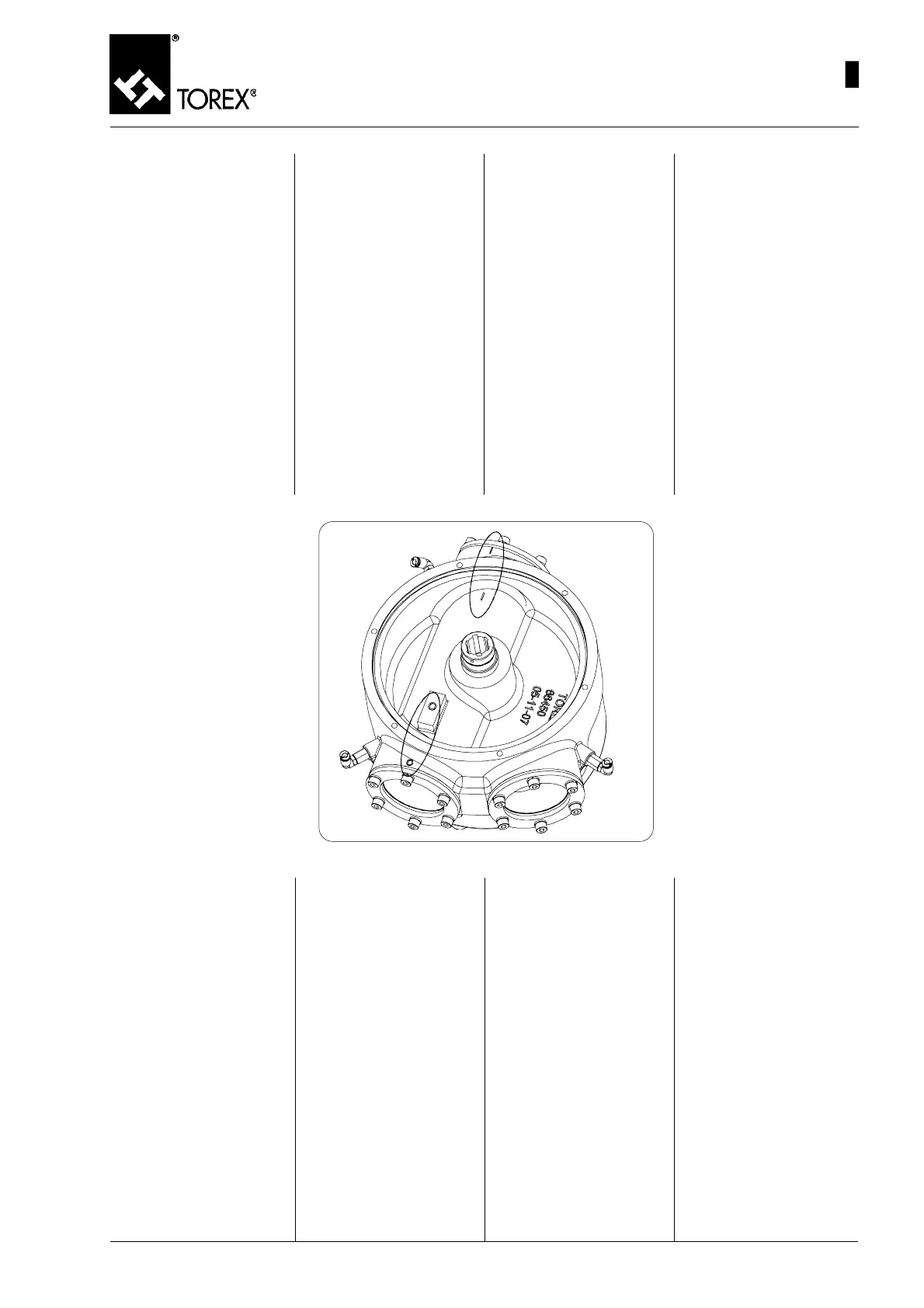
Fig. 19
2) Prima di inserire il tamburo nel
deviatore, montare le tenute
del lato folle seguendo il proce-
dimento inverso descritto nel
paragrafo “SMONTAGGIO E
SOSTITUZIONE DELLE TE-
NUTE LATO FOLLE”.
3) Una volta completato le pri-
me due operazioni, inserire il
tamburo (pos. 15, fig.18) al-
l’interno del corpo (pos. 12,
fig. 18) calandolo dall’alto fa-
cendo molta attenzione a non
danneggiare le tenute del lato
folle.
4) Per le taglie più grandi inseri-
re la ghiera filettata
IMPORTANTE: Per eseguire cor-
rettamente il montaggio, occor-
re fare riferimento ai segni “I”
ed “O” posti su corpo e tamburo
mettendoli in corrispondenza fra
loro (vedi figura 19).
Montaggio perno comando
1) Una volta inserito il tamburo
nel corpo e messo in corri-
spondenza i segni “I” ed “O”
con i loro equivalenti sulla fu-
sione del corpo, girare di 150°
il rotore in modo che il segno
“O” sul tamburo sia in corri-
spondenza del segno “I” sul
corpo. (Vedi fig. 20)
2) Questa ultima operazione è
necessaria per poter inserire il
perno comando (pos. 7, fig.
21) con il corretto orientamen-
to all’interno del tamburo (pos.
15, fig. 21).
3) Una volta ruotato il tamburo
nella posizione in cui il segno
“O” corrisponde al segno “I”,
inserire il perno con i due lati
laterali in posizione verticale,
e i due lati inferiore/superiore
in posizione orizzontale come
rappresentato nella figura 21.
37
2) Before inserting the drum in
the diverter valve, fit the idle
side seals by following the in-
verse procedure described in
the “IDLE SIDE SEALS DIS-
ASSEMBLY AND REPLACE-
MENT” paragraph.
3) When the first two operations
are complete, insert the drum
(pos. 15, Fig.18) inside the
body (pos. 12, Fig. 18) by low-
ering it from the top, taking
care to avoid damage to the
idle side seals.
4) For larger sizes, insert the
threaded ring nut
IMPORTANT: To carry out correct
assembly, refer to the “I” and
“O” markings provided on the
body and drum, keeping these
aligned (see Figure 19).
2) Bevor man die Trommel in die
Weiche steckt, die Dichtungen
auf der Seite gegenüber dem An-
trieb einbauen, wobei man das
Verfahren in der umgekehrten
Reihenfolge ausführt, das im
Abschnitt „AUSBAU UND ER-
SETZEN DER DICHTUNGEN
AUF DER SEITE GEGENÜBER
DEM ANTRIEB” beschrieben ist.
3) Wenn die ersten beiden Vorgänge
ausgeführt worden sind, die Trom-
mel (Pos. 15, Abb.18) in das In-
nere des Gehäuses (Pos. 12, Abb.
18) stecken, indem man die von
oben nach unten einführt und
besonders darauf achtet, dass
die Dichtungen auf der Seite ge-
genüber dem Antrieb nicht be-
schädigt werden.
4) Bei den größeren Baugrößen die
Gewindemutter einstecken.
WICHTIG: Um den Einbau korrekt
auszuführen, ist Bezug auf die
Markierungen „I” und „O” zu neh-
men, die sich auf dem Gehäuse
und der Trommel befinden. Diese
müssen übereinander stehen (sie-
he Abb. 19).
2) Avant d’introduire le tambour
dans la vanne déviatrice, mon-
ter les joints côté fou en sui-
vant la procédure inverse dé-
crite dans le paragraphe “DE-
MONTAGE ET REMPLACE-
MENT DES JOINTS COTE
FOU”.
3) Une fois les deux premières
opérations terminées, introdui-
re le tambour (pos. 15, fig.18)
dans le corps (pos. 12, fig. 18)
par le haut en faisant très at-
tention à ne pas endomma-
ger les joints du côté fou.
4) Pour les faille plus grandes
mettre en place la bague
filetée.
IMPORTANT: Pour effectuer cor-
rectement le montage, il faut fai-
re référence aux repères “I” et
“O” placés sur le corps et le
tambour en les alignant entre
eux (voir figure 19).
Montage de l’axe de commande
1) Une fois le tambour introduit
dans le corps et aligné aux
marques de repère “I” et “O”
avec leur équivalent sur le
corps brut de fusion, tourner
le rotor de 150° de manière à
ce que le repère “O” sur le tam-
bour soit aligné au repère “I”
sur le corps. (Voir fig. 20)
2) Cette dernière opération est
nécessaire pour pouvoir insé-
rer l’axe de commande (pos.
7, fig. 21) avec l’orientation
correcte à l’intérieur du tam-
bour (pos. 15, fig. 21).
3) Une fois le tambour tourné dans
la position où le repère “O” est
aligné au repère “I”, introdui-
re l’axe avec les deux côtés
latéraux dans la position ver-
ticale et les deux côtés infé-
rieur/supérieur dans la posi-
tion horizontale comme illus-
tré dans la figure 21.
Drive pin assembly
1) Once the drum is inserted in
the body and the “I” and “O”
markings have been aligned
with those on the body cast,
turn the rotor through 150° so
that the “O” marking on the
drum is aligned with the “I”
marking on the body. (See Fig.
20)
2) This operation is necessary to
be able to insert the drive pin
(pos. 7, Fig. 21) oriented cor-
rectly inside the drum (pos. 15,
Fig. 21).
3) After rotating the drum in the
position where the “O” mark-
ing is aligned with the “I”, in-
sert the pin with the two sides
vertical and the two lower/up-
per sides horizontal, as shown
in Figure 21.
Einbau des Steuerbolzens
1) Wenn die Trommel in das Ge-
häuse eingerastet ist und die
Markierungen „I” und „O” auf
der Höhe der entsprechenden
Marken auf dem Gussgehäu-
se stehen, den Rotor um 150°
drehen, damit die Markierung
„O” auf der Trommel auf der
Markierung “I” auf dem Gehäu-
se steht (siehe Abb. 20).
2) Dieser Vorgang ist erforderlich,
um den Steuerbolzen (Pos. 7,
Abb. 21) mit der korrekten Aus-
richtung in das Innere der
Trommel (Pos. 15, Abb. 21)
stecken zu können.
3) Nach dem Drehen der Trom-
mel in die Position, in der die
Markierung „O” mit der Mar-
kierung „I” zusammenfällt, den
Bolzen mit den beiden seitli-
chen Enden in der vertikalen
Stellung und mit dem oberen
und unteren Ende in der hori-
zontalen Stellung einstecken,
wie es in der Abbildung 21
dargestellt ist.
MAINTENANCE- DIVERTER VALVE ASSEMBLY
WARTUNG – EINBAU DER ROHRWEICHE
ENTRETIEN - MONTAGE VANNE DEVIATRICE
MANUTENZIONE - MONTAGGIO DEVIATORE
 Loading...