Page 8 ;&(%$*4.8"4,7%<'*#$"&8#=%/7*,#*%4,77%>?@@@?@AA?BCDC1 Item 57808
EF;6GH IJ6KFGLIM NFLMG6MFMO6E6GPJ
I/*(,$"83%L8#$('4$"&8#
%K*,9%$.*%6MGLK6%LNJIKGFMG%EF;6GH%LM;IKNFGLIM%#*4$"&8%,$%$.*%+*3"88"83%&2%$."#%
5,8',7%"847'9"83%,77%$*Z$%'89*(%#'+.*,9"83#%$.*(*"8%+*2&(*%#*$%'/%&(%'#*%&2%$."#%/(&9'4$1
G&&7%E*$%P/
GI%JK6!6MG%E6KLIPE%LMiPKH%;KIN%FOOLU6MGFT%IJ6KFGLIM-%
N,X*%#'(*%$.,$%$.*%J&)*(%E)"$4.%"#%"8%$.*%&22?/&#"$"&8%,89%'8/7'3%$.*%$&&7%2(&5%
"$#%*7*4$("4,7%&'$7*$%+*2&(*%/*(2&(5"83%,8V%/(&4*9'(*%"8%$."#%#*4$"&81
F$$,4.5*8$%L8#$,77,$"&8
M&$*-%%F44*##&("*#%#&79%#*/,(,$*7V1
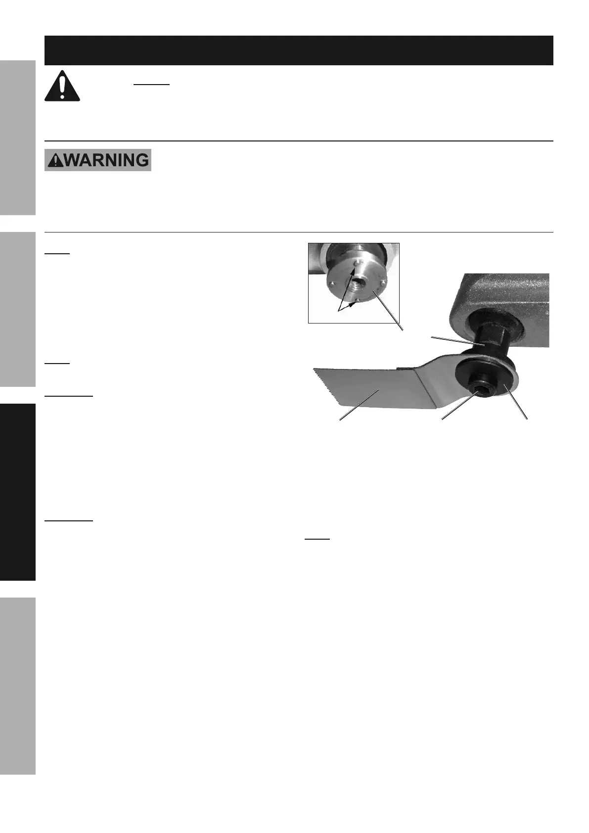
1. Use the Hex Key to remove the Cap Screw
and Flange from the end of the Spindle.
2. Install the desired accessory by placing the
accessory’s mounting holes against the fitting pins
on the Spindle. Accessories may be mounted at
angles up to 90° left or right of straight ahead.
M&$*- The long Cutter Blade should only be used
in the straight ahead position. See Figure B.
OFPGLIMj When attaching the Scraper Blade or
Cutter Blade, orient the accessory so that the blade
faces AWAY from the handle to avoid injury.
3. Replace the Cap Screw and Flange while holding
the accessory. Make sure the cupped side of
the Flange is toward the tool. While holding the
attachment over the pins on the tool, tighten the
Cap Screw onto the Spindle using the Hex Key.
G&(<'*%#8'37V%[,//(&Z"5,$*7V%>d%2$?7+\1
OFPGLIMj Make sure that the accessory is
held securely in place by the four fitting pins on
the Spindle as the Cap Screw is tightened.
;"$$"83%J"8#
E/"897*
;7,83*O'$$*(%S7,9*
O,/%E4(*)
;"3'(*%S-%%6Z,5/7*%&2%L8#$,77*9%F$$,4.5*8$%%
4. After securing, the attachment should not move
on the Spindle. If it can move with the power
off, remount it, making sure that the holes on the
attachment line up with the pins on the Spindle.
Tighten the Cap Screw securely.
M&$*- For sanding, first attach the Sanding Pad to the
tool, then align a sheet of Sandpaper over the pad and
press into place. Once a Sandpaper corner becomes
worn, turn it 120° or replace the sheet with a new one.
 Loading...