communication
Analog output
6 7 8 9 10 11
12 13 14 15 16 17 18 19
20
21
22
23
24 25 26
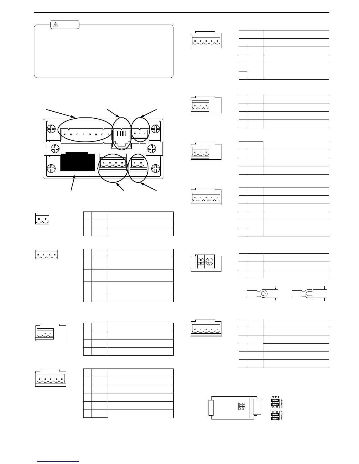
3. Terminal Arrangement
3.1 Power
3.2 External Controls
3.3 Input Signals
3.3.1 DC Voltage Measuring Unit (Range 11)
3.3.2 DC Voltage Measuring Unit (Range 12)
No. Name Description
10 POWER
Power terminal without polarity for both
DC and AC
11 POWER
Power terminal without polarity for both
DC and AC
10 11
1 2 3
Name Description
1 HI Positive input terminal
2 NC Do not connect this terminal.
3 LO
No.
Negative input terminal
Name Description
1 12
Positive input terminal for range 12
(±999.9 mV)
2 13
3 14
No.
1 2 3 4 5
4 15
5 LO Negative input terminal
Positive input terminal for range 13
(±9.999 V)
Positive input terminal for range 14
(±99.99 V)
Positive input terminal for range 15 (±600
V)
3.3.3 DC Current Measuring Unit
3.3.4 AC Voltage Measuring Unit (Ranges 11 to 13)
3.3.5 AC Voltage Measuring Unit (Ranges 14 and 15)
3.3.6 AC Current Measuring Unit (Ranges 23 to 25)
3.3.7 AC Current Measuring Unit (Range 26)
3.3.8 Resistance Measuring Unit
1 2 3 4 5
Name Description
1 23
Positive input terminal for range 23
(±9.999 mA)
2 24
3 25
No.
4
LO
5
Negative input terminal
Positive input terminal for range 24
(±99.99 mA)
Positive input terminal for range 25
(±999.9 mA)
1 2 3
Name Description
1 11-12
Positive input terminal for ranges 11
(99.99 mV) and 12(999.9mV)
2 13
3
No.
LO
Positive input terminal for range 13 (9.999
V)
Common input terminal
1 2 3
Name Description
1 14
Positive input terminal for range 14 (99.99
V)
2 15
3
No.
LO
Positive input terminal for range 15 (600
V)
Common input terminal
1 2 3 4 5
Name Description
1 23
Positive input terminal for range 23 (9.999
mA)
2 24
3 25
No.
4
LO
5
Negative input terminal
Positive input terminal for range 24 (99.99
mA)
Positive input terminal for range 25 (999.9
mA)
5.8 mm
min.
5.8 mm
min.
Applicable solderless terminals
1 2
Name DescriptionNo.
1 HI Inputterminal
2 LO Inputterminal
1 2 3 4 5
Name Description
1 HI Input terminal for all ranges
2 LO
3 +S
No.
4
LO5
Common terminal (grounding terminal for
input circuit)
Input terminal for all ranges
Constant current for four-wire resistance
measurement(positive)
-S
Constant current for four-wire resistance
measurement(negative)
Name Description
6 HOLD
Control for hold function. Enabled when
short-circuited or at the same potential as
COM.
7 DZ
Control for digital zero function. Enabled
when short-circuited or at the same
potential as COM.
6 7 8 9
8
9
PH
COM
No.
Control for peak hold function. Enabled
when short-circuited or at the same
potential as COM.
Common for all external control terminals.
(1) Mounttheproducttoapanelthatisstrongenoughtoholdtheproduct.
Ifthepanelisnotstrongenoughortheproductisnotfixedtightly,it
mayfalldownandcauseinjury.
(2) TheA5000doesnothaveapowerswitch,andwillthusbeimmediately
readyforoperationuponconnectingittoapowersupply.
(3) Iftheproductisinstalledinsideotherequipment,providesufficientheat
dissipationtoensurethatthetemperatureinsidetheequipmentdoes
notexceed50℃.
Caution
!
※ Settothe4- wiresystem whensh ipped.
W henchangingtothe2 -w iresystem ,loca te
theST1soc ketontheresistan cem ea surem ent
un ittoth e“2”pos itions.
4-wire
2-wire
 Loading...