Instruction Manual for A5000 Series
3/12
3.3.9 Temperature Measuring Unit (TC)
3.3.10 Temperature Measuring Unit (RTD)
3.3.11 Frequency Measuring Unit (Open collector, logic, and magnet)
3.3.12 Frequency Measuring Unit (500 Vrms)
3.3.13 Strain Gauge Input Unit (Load cell)
3.3.14 Process Signal Measuring Unit
3.4 Comparison Output
1 2 3 4 5
Name Description
1 HI Positiveinputterminal
2 LO
3 +15V
No.
4
COM5
Commonterminal(groundingterminalfor
inputcircuit)
Negativeinputterminal
Poweroutputforsensor(positive)
0V Poweroutputforsensor(negative)
1 2 3
Name Description
1 HI Inputterminal
2 NC
3
No.
LO
Donotconnectthisterminal.
Inputterminal
1 2 3 4 5
Name Description
1 +SIG Positiveinputterminal
2 -SIG
3 +EXC
No.
4
COM5
Commonterminal(groundingterminalfor
inputcircuit)
Negativeinputterminal
Poweroutputforsensor(positive)
-EXC Poweroutputforsensor(negative)
1 2 3
Name Description
1 V-IN Positiveinputterminalfor1to5Vrange
2 A-IN
3
No.
LO
Positiveinputterminalfor4to20mArange
Negativeinputterminal
12 13 14 15 16 17 18 19
Name Description
12 LO-b LOoutputterminal(bcontact)
13 LO-c
14
No.
LO-a
CommonterminalforLOoutput
LOoutputterminal(acontact)
15 GO-c CommonterminalforGOoutput
16 GO-a
17 HI-b
GOoutputterminal(acontact)
HIoutputterminal(bcontact)
18 HI-c
19 HI-a
CommonterminalforHIoutput
HIoutputterminal(acontact)
3.5 Analog Output
3.6 Serial Communication
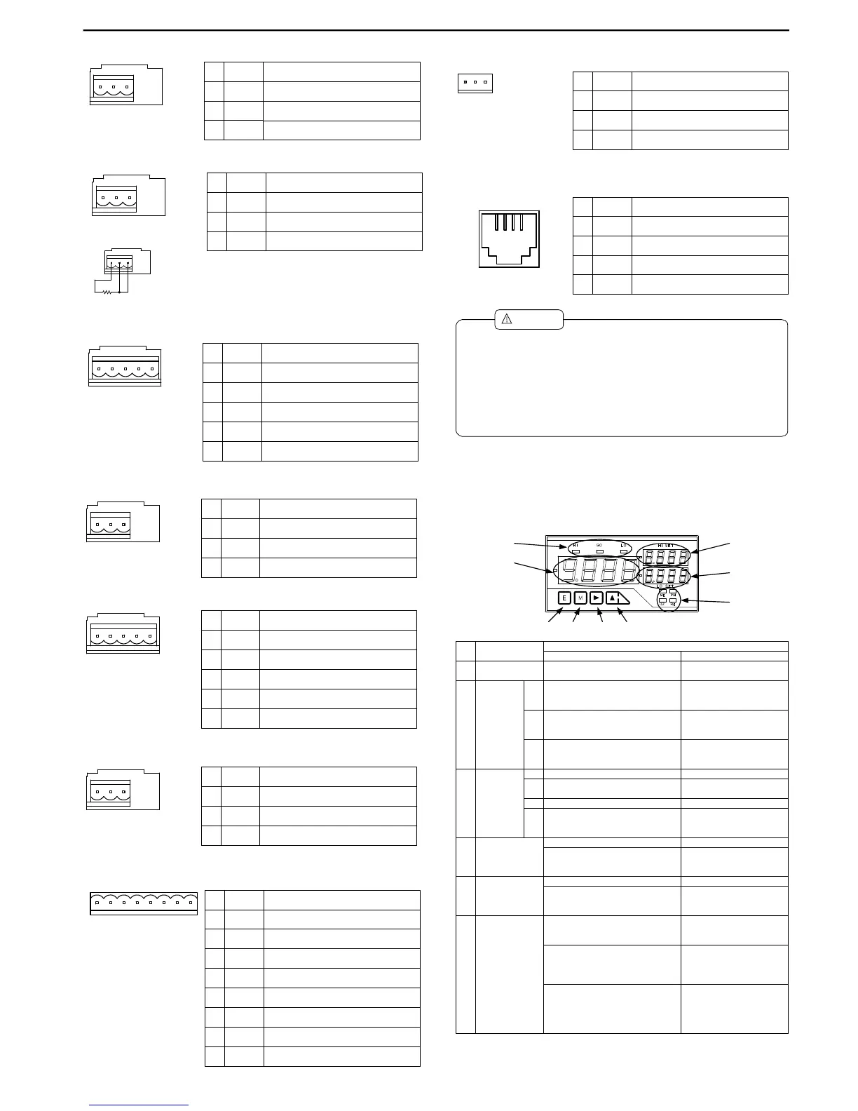
4. Components and their Functions
The front panel design of the A5000 series of unit meters differs depending on the
display unit selected. The names and functions of each unit are as shown below.
4.1 Multi-display Unit
24 25 26
Name Description
24 COM Commonterminalforanalogoutput
25 A-OUT
26
No.
V-OUT
Currentoutputterminal(4to20mA)
Voltageoutputterminal(1to5V,0to1V,
and0to10V)
20212223
Name Description
20 RXD(+)
RS-232C:transmission;
RS-485:Non-reverseoutput
21 TXD(-)
22
No.
NC
RS-232C:reception;
RS-485:Reverseoutput
Donotconnectthisterminal.
23 SG Commonterminalforcommunications
(2)(3)(4)(5)
Modularjack:
RJ-14(6P4C)
(1) Use12to28AWGwireforthepower,input(exceptforrange26),
externalcontrol,andcomparisonoutputconnectors.
(2) Tightenthescrewsforthepower,input(exceptforrange26),external
control,andcomparisonoutputconnectorstoatorqueof0.5to0.6Nm.
(3) Use16to28AWGwirefortheanalogoutputconnector.
Tightenthescrewsofanalogoutputconnectortoatorqueof0.22to
0.25Nm.
(4)
Caution
!
Eachwiringexceptapowersupplyisgivenasunderfull-length30m.
(5)
If30misexceeded,itwillbecomeoutofthescopeofEN/IECstandard.
(1)
(2)
(3)
(4)
(6) (7) (8) (9)
(5)
No. Name
MainFunctions
Duringmeasurement Duringparametersetup
(1) Maindisplay Indicatesthemeasuredvalue.
IIndicatesinformationonthe
parametertobeset.
Judgment
indicators
HI
(2) GO
LO
Indicatestheresultofjudgmentand
turnsonifthemeasuredvalue>HI
judgmentvalue.
Indicatestheresultofjudgmentand
turnsonifLOjudgmentvalue≦the
measuredvalue≦HIjudgmentvalue.
Indicatestheresultofjudgmentand
turnsonifthemeasuredvalue<LO
judgmentvalue.
(3)
Function
indicators
ME Turnsonif“digitalzerobackup”ison.
PH
Turnsonif“peakhold/valleyhold/
peak-valleyhold”ison.
Turnsonif“digitalzero”ison.DZ
RE
Turnsonifremotecontrolisbeing
performedthroughRS-232CorRS-
485interface.
(4) Sub-display1
IndicatestheHIsidejudgmentvalue.
Indicatestheiteminthemaximum/
minimum/(maximum-minimum)/input
valuemonitoringmode.
IndicatestheLOsidejudgmentvalue.
Sub-display2(5)
Indicatesinformationontheitemin
themaximum/minimum/(maximum-
minimum)/inputvaluemonitoringmode.
Indicatestheitemtobeset.
(6) Enterkey
PressingtheEnterandModekeys
togetherchangestotheparameter
settingmode.
PressingtheEnterandIncrementkeys
togetherchangestothemaximum/
minimum/(maximum-minimum)/input
valuemonitoringmode.
Switchesfromthemaximum/
minimum/(maximum-maximum/
minimum/(maximum-minimum)/input
valuemonitoringmodetothe
comparativejudgmentreadingmode.
Returnstothemeasurement
mode.
1 2 3
Name Description
1 + Positive terminal for thermocouple
2 NC
3
No.
-
Do not connect this terminal.
Negative terminal for thermocouple
Connectionofthree-wiresensor
1 2 3
Name Description
1 A Resistancesensorwire
2 B
3
No.
C Eliminationofwireresistance
Resistancesensorwire
Theanalogoutputatthetimeofaburnoutbecomes+side
atthetimeofAorBdisconnection,andissetto0Vor1V,
and4mAatthetimeofCdisconnection.
WhenAorBisdisconnection,itisdisplayedasOL,andwhen
Cisdisconnection,itisdisplayedas----.
 Loading...