Instruction Manual for A5000 Series
7/12
Note: For the process signal measuring unit, set the full scale input value to
5.000 for the 1 V range and to 20.00 for the 2 A range, and set the offset
input value to 1.000 for the 1 V range and to 4.00 for the 2 A range.
The following explains the frequency measuring unit. (The same method applies
to the full scale indication parameter.)
Note: For the frequency measuring unit, set the relationship between the input
and indication using the PS and PPR parameters (parameters of FSC,
FIN, OFS, and OIN are not indicated).
The following explains the scaling of analog output (The same method applies to
the full scale indication parameter.)
Note1: For analog output scaling, set the indication value for an output current
of 20 mA in the AOHI parameter and set the indication value for an
output current
o
f 4 mA in the AOLO parameter (for 4-20 mA output).
Note2: The analog signal out of the setting range cannot be accurately output.
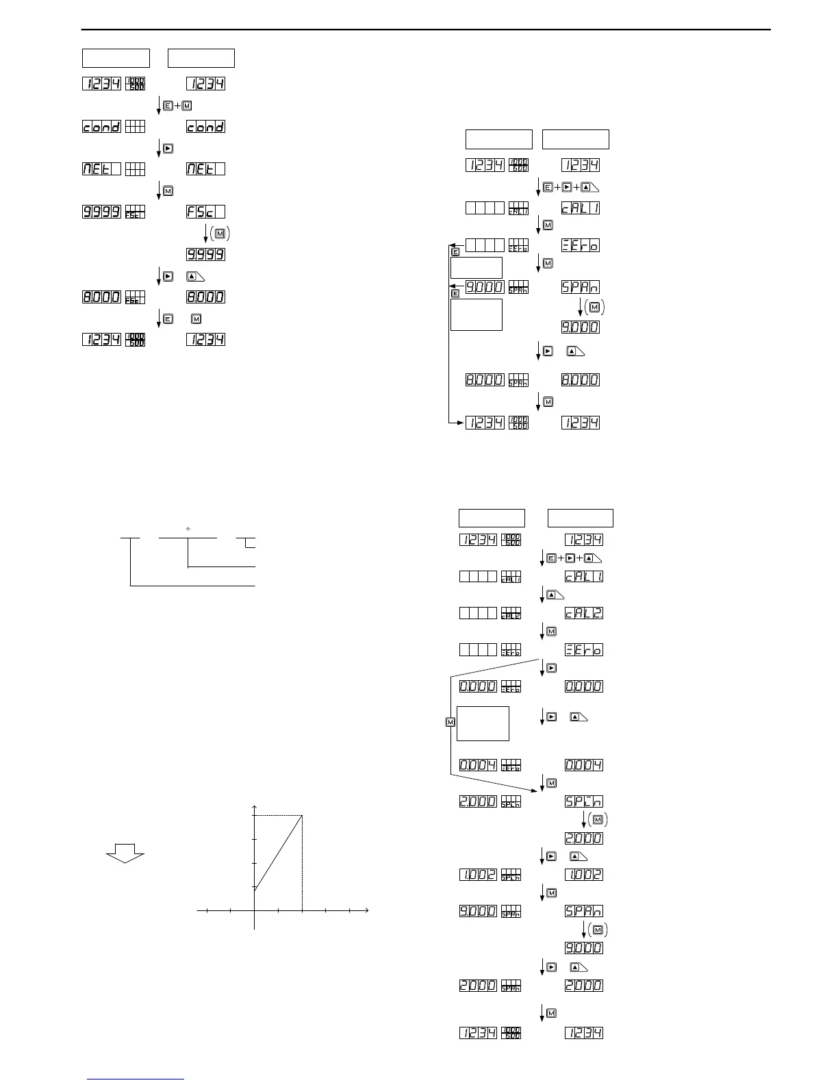
Multi-display unit Single display unit
or
(1) Press the Mode and Enter keys together
during measurement.
(2) Press the Shift key a few times to change to
the scaling data menu.
(6) Pres s the E nt er k ey to ret urn t o t he
measurement mode (Pressing the Mode key
changes to the next parameter).
(5) Press the Shift key (change digit) and press
the Increment key (change numeric value) to set
to 10.
&
Note:The decimal point in the selected digit
flashes.
(3) Press the Mode key a few times to display the
parameter to be set.
(4) For a single display unit, press the Mode key
to change to the parameter information indication.
(The dis play automatically changes to this
indication in about 1 second, except for parameter
FSC right after MET is indicated.)
Determiningtherevolutionspeed(rpm)usingtherotaryencodersetto30pulsesperminute:
(1)Determinethemeasurementrangebycalculatingthemaximumfrequency.
Thefigurebelowshowsanexamplewheretherevolutionrisestoamaximumspeedof
about100rpm.
30 × 100 60
Revolutionspeedpersecond
Numberofpulsesperrevolutionatthe
rotaryencoder
= 50
Numberofpulsespersecond
(3)Thedisplayunitshows500if50Hzpulseinputismeasuredunderrange11(whenPS=1
thedecimalpointispositionedinthe10
1
digit(100.0isisindicated50Hzinput).
(2)Sincethenumberofpulsesdeterminedin(1)is50persecond(50Hz),settherangeto
range11(forhowtosettherange,seethesectiononsettingconditiondata).
Indication
:
4 to 20mA
0.0 to 500.0
:
Output
AOHI : 5000
AOLO : 0
Output
Indication
20mA
5000
4mA
0
5.4.4 Method of Setting Calibration Data
5.4.4.1 Actual Load Calibration
Actual load calibration means that calibration is carried out by applying actually
measured pressure to a sensor such as a load cell connected to the meter.
5.4.4.2 Equivalent Calibration
Equivalent calibration means that calibration is carried out according to the rat-
ings (specifications) of such a sensor as a load cell. It is not necessary to connect
the sensor or to apply pressure to the sensor.
Multi-display unit Single display unit
(1) Press the Shift, Increment, and Enter keys
together during measurement.
(2) Press the Mode key to change to the actual
load calibration mode.
(6) Press the Mode key to return to the
measurement mode.
(5) Press the Shift key (change digit) and
Increment key (change numeric value) to
set 8000.
&
Note:The decimal point in the selected digit
flashes.
(3) Press the Mode key while applying
pressure that will cause the display to show
zero.
(4) For a single display unit, press the Mode
key to change to the parameter information
indication.
Err1:
When the input at the time of zero calibration
is below -0.3mV/V, it displays.
Err2:
When the input at the time of zero
calibration is more than 1mV/V, it displays.
Err3: It is the same as that of the time of being an
input at the time of span calibration at the zero
proofreading time, or when small, it displays.
Err4:
When the input at the time of span calibration
is more than 3.3mV/V, it displays.
Err5:
When the setup more than the highest
decomposition ability is performed, it displays.
WhentheEnterkeyis
pressed,itreturnsto
measurementmode.
WhentheEnterkeyis
pressed,itreturnsto
measurementmode
withZeroinputvalue
only.
(1) Press the Shift, Increment, and Enter key
together during measurement.
(2) Press the Increment key to select the
equivalent calibration mode.
(12) Press the Mode key to return to the
measurement mode.
(11) Press the Shift key (change digit) and the
Increment key (change numeric value) to set 2000.
&
Note:The decimal point in the selected digit
flashes.
(4) Press the Shift key to display the zero-input
setup mode.
(10) For a single display unit, press the Mode key
to display the parameter information indication.
(3) Press the Mode key to move to the equivalent
calibration mode.
&
(5) Press the Shift key (change digit) and the
Increment key (change numeric value) to set 0.004.
Note:The decimal point in the selected digit
flashes.
Note:For a single display unit, the unit
automatically returns to ZERO indication if
there is no key operation for about 8 seconds.
In such a case, press the Mode key to return
to the numerical value indication.
(6) Press the Mode key to change to the span
input value setup mode.
&
(7) For a single display unit, press the mode key
to display the parameter information indication.
(8) Press the Shift key (change digit) and the
Increment key (change numeric value) to set
1.002.
(9) Press the Mode key to change to the span
indicating value setup mode.
Multi-display unit Single display unit
Err1:
When the input at the time of zero
calibration is below -0.3mV/V, it displays.
Err2:
Whentheinputatthetimeofzero
calibrationismorethan1mV/V,itdisplays.
Err3: Itisthesameasthatofthetimeofbeingan
inputatthetimeofspancalibrationatthe
zeroproofreadingtime,orwhensmall,it
displays.
Err4:
Whentheinputatthetimeofspancalibration
ismorethan3.3mV/V,itdisplays.
Err5:
Whenthesetupmorethanthehighest
decompositionabilityisperformed,itdisplays.
PresstheModekey
whileapplying
pressurethatwill
causethedisplayto
showzero.
 Loading...