EasyManua.ls Logo

Waterous E501-A - User Manual

Waterous E501-A
16 pages
Print Icon
To Next Page IconTo Next Page
Loading...
E500 Series Motor Pump
Operation, Maintenance
and Overhaul Instructions
Form No.
F-2390
Issue Date
09/04
Rev. Date
3/27/17
Table of Contents
W
Read through the safety information and
operating instructions carefully before
using your Waterous Fire Pump.
Visit us at www.waterousco.com
Waterous Company 125 Hardman Avenue South, South St. Paul, Minnesota 55075 USA (651) 450-5000
Instructions subject to change without notice.
E511 Impeller and Mechanical Seal Removal -------------------- 8
Safety Instructions ------------------------------------1, 2
Introduction ------------------------------------------------- 3 E501 Gear Case Cover and Impeller Shaft Removal---------- 8
Installation ------------------------------------------------ 3 E511 Gear Case Cover and Impeller Shaft Removal-------------9
Fire Hose Testing---------------------------------------- 4 E501 Impeller Shaft Assembly------------------------------------------9
Maintenance and Repair------------------------------- 5 E511 Impeller Shaft Assembly----------------------------------------10
Preparation----------------------------------------------- 5 E501, E511 Gear Case Removal-------------------------------------10
Operation----------------------------------------------- 5 E501, E511 Engine Adapter Removal-------------------------------11
Starting the Engine-------------------------------------- 5 E501, Mechanical Seal Assembly------------------------------------11
Priming the Pump--------------------------------------- 5 E511 Mechanical Seal Assembly-------------------------------------12
Setting the Throttle---------------------------------------5 Inspection----------------------------------------------------------------------13
Engine Maintenance------------------------------------ 6 Impeller Wear--------------------------------------------------------------13
Pump Maintenance------------------------------------- 6 Mechanical Seal-----------------------------------------------------------13
Engine Repair------------------------------------------- 6 Oil Seals---------------------------------------------------------------------13
Pump Repair--------------------------------------------- 6 Reassembling and Testing-----------------------------------------------13
Overhaul----------------------------------------------------- 7 Reassembling the Pump------------------------------------------------13
E501 Volute Body Removal------------------------ 7 Testing-----------------------------------------------------------------------14
E511 Volute Body Removal------------------------ 7
E501 Impeller and Mechanical Seal Removal
Question and Answer IconNeed help?

Do you have a question about the Waterous E501-A and is the answer not in the manual?

Overview

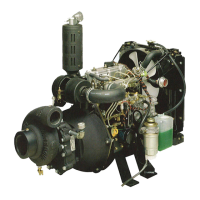
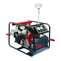
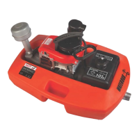
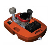
The Waterous E500 Series Motor Pump is a gear-driven centrifugal pump designed for fire pump applications. It is powered by a three-cylinder, 952 cc diesel or gasoline Briggs & Stratton Vanguard engine. The pump unit is designed for operation, maintenance, and repair, with specific instructions provided for each aspect.

Function Description

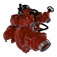
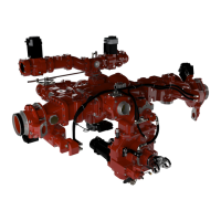
The primary function of the E500 Series Motor Pump is to provide a reliable and efficient means of pumping water, typically for fire suppression. It achieves this by converting mechanical energy from the engine into hydraulic energy to move water at high pressure and volume. The pump can be integrated into fire apparatus, offering various control panel options including a Municipal Panel, Deluxe Panel, Main Panel, and an Optional In-Cab Panel, allowing for flexible installation and operation depending on the application's needs. The pump's design incorporates a volute body, impeller, and mechanical seal system to efficiently move water.

Usage Features

The E500 Series Motor Pump offers several usage features to ensure effective and safe operation:

  • Starting the Engine: Different starting procedures are outlined based on the engine type and control panel. For E501-A and E511-A models with a Deluxe Engine Panel, the process involves pumping the fuel filter primer, turning the ignition switch to RUN and waiting for the glow lamp to shut off, then holding down the manual reset button while turning the ignition to START until sufficient oil pressure is obtained. For the same models with a Municipal Panel, the process is similar but without the manual reset button step. The E511-B gasoline model requires pulling the choke knob and turning the ignition switch to START, adjusting the choke as needed.
  • Priming the Pump: All models require priming to ensure proper water flow. This involves using an intake strainer to prevent foreign matter from entering the pump and following specific instructions for the optional priming pump system (F-1031, Section 2312).
  • Setting the Engine Throttle: After priming, the engine throttle can be adjusted to achieve the desired pump performance.
  • Connections: Leak-proof connections between the pump intake and discharge hoses or piping are crucial. For permanently mounted units, flexible couplings are recommended to prevent excessive forces on the pump.
  • Shut Down: After use, the engine speed should be returned to idle, and the ignition switch turned to the OFF position. The volute body must be drained by opening the drain cock to prevent damage, especially in freezing conditions.
  • Safety Precautions: The manual emphasizes numerous safety warnings, including those related to exhaust gas and fire hazards (e.g., not running the engine in enclosed areas, proper refueling), pressure hazards (relieving pressure before connecting/removing hoses), scalding water hazards (opening a discharge valve slightly to prevent overheating), accidental starting hazards (disconnecting battery during servicing), and moving/rotating parts hazards (keeping hands and feet clear). Special warnings are also provided for fire hose testing, noting that fire pumps on apparatus are not designed for this purpose and specific NFPA 1962 procedures must be followed if used.

Maintenance Features

Regular maintenance is critical for the longevity and optimal performance of the E500 Series Motor Pump:

  • Preparation: Before initial operation, the unit must be inspected for shipping damage. The engine is shipped without oil and coolant, which must be added according to Briggs & Stratton instructions. A 12 VDC battery with a minimum capacity of 380 Amps (63 Amp-hours) must be installed. The transmission requires 1 pint of SAE 90 oil. The fuel tank must be filled with recommended fuel. The engine crankshaft should be rotated to ensure free movement.
  • Engine Maintenance: Refer to the Briggs & Stratton Operation and Maintenance instructions for specific engine maintenance information. Maintaining the correct oil level is crucial to prevent engine power loss, personal injury, or property damage.
  • Pump Maintenance:
    • Volute Body Drainage: The volute body should be drained after each use. If chemicals, salt water, or dirty water have been handled, the entire system must be flushed with clean, fresh water for several minutes.
    • Gear Case Oil: The gear case oil level should be checked monthly and filled as needed. The gear case oil should be changed yearly or every 100 hours of pump operation, whichever comes first. This involves removing the magnetic drain plug, disposing of old oil properly, replacing the drain plug, and refilling as described in the "Preparation" section.
  • Overhaul and Repair:
    • Pump Repair: Pump repair should be performed by Waterous authorized service personnel or by a mechanic familiar with pump overhaul practices. Service Parts Lists are provided for ordering parts, requiring the pump model, serial number, and parts list number.
    • Engine Repair: For engine service or repair, refer to the Briggs & Stratton Operation and Maintenance instructions. Waterous Company supplies the control panel, wiring harness, and pump drive system.
    • Disassembly and Reassembly: Detailed instructions are provided for disassembling and reassembling various pump components, including the volute body, impeller, mechanical seal, gear case cover, impeller shaft, engine adapter, and drive plate. Specific steps are outlined for removing and installing parts like hex head screws, nuts, washers, impellers, keys, mechanical seals, bearings, and oil seals.
    • Inspection: During overhaul, components should be inspected for wear. This includes checking the impeller for excessive wear or clearance, inspecting O-rings for cuts or nicks, and examining the mechanical seal for damage. Ball bearings and needle bearings should be checked for wear. Oil seals should be inspected for signs of wear.
    • Reassembling and Testing: Instructions for reassembling the pump emphasize proper lubrication of mechanical seal components (bellows, O-rings, sealing faces) and careful installation of parts to prevent damage. Specific steps are provided for installing the impeller shaft assembly, ensuring the mechanical seal is properly seated, and reassembling the gear case and volute body. After reassembly, the pump should be tested for leaks and proper operation. The testing procedure involves running the pump, checking for unusual noises, and verifying that the pump is returned to service only after all seals run-in.

The manual stresses the importance of reading all safety and operating instructions carefully before using the Waterous Fire Pump to ensure safe and effective operation and maintenance.

Waterous E501-A Specifications

General IconGeneral
Pump ModelE501-A
CategoryFire Pump
TypeSingle Stage, Centrifugal
Rated Capacity500 GPM
ManufacturerWaterous
Rated Pressure150 PSI
Discharge Size2.5 inch
Intake Size4 inch
Power SourceEngine Driven

Related product manuals