The Watlow Series L is a range of temperature limit controllers designed for applications requiring thermal system protection. These controllers prevent over or under-temperature conditions, providing safety assurances against thermal runaway due to failed sensors, controllers, or output devices. They are recommended for applications where thermal runaway could lead to product scrap, equipment damage, fire hazards, or personnel risk. Both LF and LV models are Factory Mutual and CSA approved.
Function Description:
The Series L controllers act as safety limits, interrupting power to a process if the temperature exceeds or falls below a set limit. This prevents hazardous situations during abnormal equipment operation.
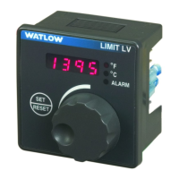
- Series LF and LV: These models provide temperature limit control. The LV models include an operator interface for viewing and adjusting the limit set point, while LF models have fixed limit set points and no operator interface.
- Series LS: This control meets the latest safety standards for food service equipment (UL/EN 60335) and is approved to UL/EN 60730-1 and 60730-2-9 Electronic Control Thermal Cut-out Class II with Class B Software review. It offers enhanced safety through factory-fixed set points, factory-fixed hysteresis, and redundant temperature sensors to protect against single-point sensor failure. The LS can initiate an over-temperature limit if either sensor fails or if the deviation between sensors exceeds a process comparison value. It requires a power cycle to reset once tripped.
Important Technical Specifications:
- Controller Type: Microprocessor-based, limit controller.
- Nominal Switching Hysteresis: Typically 1.7°C (3°F).
- Output: High or low limit, factory selectable.
- Reset: Manual or automatic reset on power loss, factory selectable. Manual reset requires an external reset switch (LF/LV only). LS models require a power cycle to reset.
- Operator Interface (Model Dependent):
- LV (1, 2, 5 or 6): Four-digit, 7-segment LED display, .28" high (not available on model LS). °F or °C indicator LED. ALARM indicator LED. Continuous turn, velocity-sensitive rotary encoder for limit set point adjustment. Front panel SET/RESET key for variable set point models.
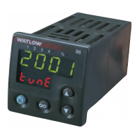
- LV (A, B, C or D): Four-digit, 7-segment LED display, .28" high. °F or °C indicator LED. ALARM indicator LED. Increment and Decrement keys for limit set point adjustment. Front panel SET/RESET key for variable set point models.
- Standard Conditions For Specifications: Rated line voltage ±10%, 50 to 60Hz, 0 to 90% RH non-condensing, 15-minute warm-up.
- Calibration Ambient Range: 25°C (77°F) ±3°C.
- Sensor Input:
- Thermocouple: Grounded or ungrounded. Models LF, LV, LS support Type J, K, T thermocouples. Input impedance >10 MΩ. 250 nV input referenced error per 1 Ω source resistance.
- RTD (LF/LV only): 2-wire platinum, 100 Ω. DIN curve (.00385 curve). 125 µA nominal RTD excitation current.
- RTD Input Accuracy Span Range:
- Type J: -200 to 1038°C or -328 to 1,900°F.
- Type K: -200 to 1370°C or -328 to 2,500°F.
- Type T: -200 to 400°C or -328 to 750°F.
- RTD (DIN): -200 to 800°C or -328 to 1,472°F.
- Calibration accuracy: ±1% of input accuracy span, ±1°C in standard conditions and actual calibration ambient.
- Exception: Type T, ±2.4% of input accuracy span for -250 to 0°C (-418 to 32°F).
- RTD Input Temperature Stability: ±0.3 degree per degree change in ambient.
- RTD Input Calibration Accuracy: ±1% at standard conditions and actual calibration ambient.
- RTD Input Temperature Stability: ±0.2 degree per degree change in ambient.
- Allowable Operating Ranges:
- Type J: -200 to 800°C or -328 to 1,470°F.
- Type K: -210 to 1193°C or -346 to 1,900°F.
- Model LS: 0 to 330°C or 32 to 626°F.
- Model LS: -18 to 438°C or 0 to 764°F.
- Type T: -270 to 400°C or -454 to 750°F.
- Model LS: 0 to 438°C or 32 to 820°F.
- Type E: -270 to 700°C or -454 to 1,292°F.
- RTD (DIN): -200 to 800°C or -328 to 1,472°F.
- External Reset Switch (LF/LV only): Momentary, dry contact closure. See wiring section.
- Output Types:
- Electromechanical Relay, Form C (LF/LV only): Minimum load current: 100 mA. 8 A @ 240V~ (ac) or 30V= (dc) maximum, resistive. 250 VA pilot duty, 120/240V~ (ac) maximum, inductive. Use RC suppression for inductive loads. Electrical life 100,000 cycles at rated current.
- Electromechanical Relay, Form A (LS only): Minimum load current: 100 mA. 8 A resistive load. 120 VA pilot duty, 120/240V~ (ac) maximum, inductive. Electrical life 6,000 cycles at rated current.
- Agency Approvals:
- Series LF (potted version only): UL 991 recognized temperature limit for food service industry. RoHS Directive (2002-95-EC).
- Series LV and Series LF (including potted version): UL 873 recognized temperature regulator. File #E63684. UL 197 recognized for use in food service appliances. ANSI Z21.23 Gas appliance thermostat approval. CSA C22.2#24 approved temperature control. File #05886. FM Class 3545 temperature limit switches. File #3017239. NEMA 4X/IP65 on panel-mount versions with tactile keys for set point adjustment. W.E.E.E.; CE – see Declaration of Conformity. RoHS Directive (2002-95-EC).
- Series LS (potted version only): UL/EN 60730-1, Type 2, B, K Automatic Electronic Controls for household and similar use. UL 1998 Software review Class B. Sensor differential – 20°/36°F. Thermal Limit.
- Terminals: 6.4 mm (0.25 in) quick connect, push-on terminals. Removable screw clamp style terminal blocks. Wire gauge 0.1 to 4 mm² (30 to 12 AWG). Strip length: 8 mm (0.31 in). Torque: 0.8 N-m (7 in-lb) maximum.
- Power:
- 24V~ (ac) +10%; -15%; 50/60 Hz, ±5%.
- Model LS 100 - 240V~ (ac) +10%; -15%; 50/60 Hz, ±5%.
- 120V~ (ac) +10%; -15%; 50/60 Hz, ±5%.
- 208 to 240V~ (ac) +10%; Series LF and CF only.
- 230 to 240V~ (ac) +10%; -15%; 50/60 Hz, ±5%.
- 10 VA maximum power consumption.
- Data retention upon power failure via nonvolatile memory.
- Operating Environment: 0 to 70°C (32 to 158°F). 0 to 90% RH, non-condensing. Storage temperature: -40 to 85°C (-40 to 185°F).
- Dimensions: DIN Rail model can be DIN rail or chassis mount. DIN rail spec, DIN 50022, 35 mm x 7.5 mm (1.38 in x 0.30 in).
- Open Board: Width 61.7 mm (2.43 in), Height 45.07 mm (1.775 in), Depth 48.1 mm (1.89 in).
- All Potted Versions: Width 70.1 mm (2.76 in), Height 102.9 mm (4.05 in), Depth 46.6 mm (1.84 in).
- DIN Rail: Width 78.1 mm (3.08 in), Height 112.3 mm (4.42 in), Depth 90.7 mm (3.57 in).
- Square 1/8 DIN Panel: Width 72.4 mm (2.85 in), Height 72.4 mm (2.85 in), Depth 51.7 mm (2.04 in).
Usage Features:
- Four-Character LED Display: Indicates the limit set point.
- Fixed or Adjustable Limit Set Points: LF models have fixed set points, while LV models offer adjustable set points via a rotary encoder or increment/decrement keys.
- Tamper-Proof Operation: Reduces accidental limit set point adjustments (Push to Set on LV models).
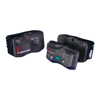
- Multiple Mounting Options: Available in 1/8 DIN panel mount, DIN rail mount, open board, or potted module designs.
- Fahrenheit or Celsius Operation: Indication on the display.
- Sensor Break Protection: Provides positive system shutdown in case of sensor failure.
- Micro-Processor Based Technology: Ensures accurate and repeatable protection.
- Dual Channel Sensors (LS models): Detects sensor faults and provides fault-tolerant design.
- Fail Safe Design: Internal or external faults cause the product to shut-down in a safe manner.
- Calibration Offset (Tactile Keys): Allows adjustment of calibration offset (range: -30 to 30°) by holding Increment and Decrement keys for five seconds.
- Temperature Unit Change (Tactile Keys): Allows switching between °F and °C by holding Increment and Decrement keys for ten seconds.
Maintenance Features:
- Troubleshooting Guide: Provides indications, possible causes, and corrective actions for common issues such as:
- Display not illuminated.
- Incorrect temperature readings (sensor errors, ALARM LED switching incorrectly).
- Temperature discrepancies (decreasing when increasing, low reading when increasing, offset from actual).
- Both LEDs alternating flashing (LS controller).
- ALARM not tripping or tripping when it shouldn't.
- Limit output signal on when it should be off.
- Unable to reset controller after limit trips.
- LS LED Definition: Explains the meaning of different LED statuses (Limit/Range flashing, on, off, alternate) to indicate limit conditions, reset status, normal operation, ambient alarms, and health check errors.
- Warranty: All Watlow Series L limit controllers come with a three-year warranty.
- Return Material Authorization (RMA): A process for returning products, requiring prior approval and an RMA number. This includes procedures for defective products, non-defective returns, and no trouble found (NTF) returns.