2
Guidelines
Most field problems occur because dirt and debris present in
the system at the time of installation becomes trapped in the
#1 check. The system should be flushed before the backflow
valve is installed. If the system is not flushed until after the
backflow valve is installed, remove both check modules from
the valve and open the inlet shutoff to allow water to flow for
a sufficient time to flush debris from the water line. If debris in
the water system continues to cause fouling, a strainer can be
installed upstream of the backflow assembly.
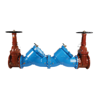
Watts models 757 and 757DCDA/LF 757DCDA may be
installed in either horizontal or vertical position as long as the
backflow assembly is installed in accordance with the direction
of the flow arrow on the assembly and the local water authority
approves the installation. The assembly should be installed with
adequate clearance around the valve to allow for inspection,
testing and servicing. 12" should be the minimum clearance
between the lower portion of the assembly and the floor or
grade.
Note: Assembly body should not be painted.
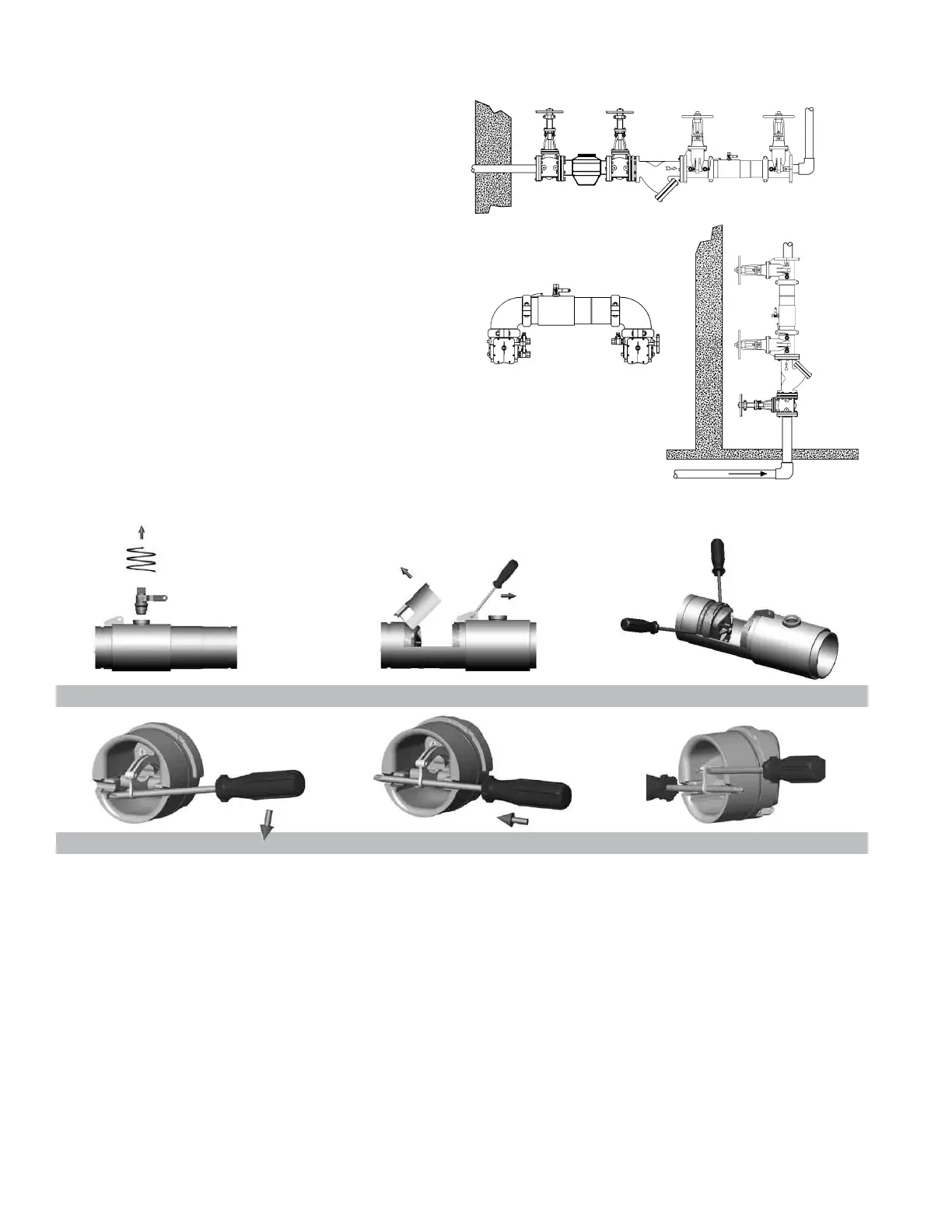
Horizontal Installation
N Pattern
Vertical
Installation
Figure D
Figure E
Figure F
Figure A
Figure B
Figure C
Prior to servicing any Watts valve, it is mandatory to shut
down the water system by closing both the inlet and outlet
shutoff valves. After shutoff valves are closed, open test
cock #2, #3 and #4 to relieve pressure within the backflow
assembly.
1. After #3 test cock has been opened to relieve pressure,
remove #3 test cock from housing. (Figure A)
2. Insert a #3 screwdriver through the hole on the top of the
cover sleeve and using both hands rotate the cover sleeve
approximately
1
/4-turn clockwise and
1
/4-turn counter-clock-
wise to break the sleeve O-ring seals. Using the screwdriver,
slowly slide the cover sleeve to the downstream side of the
housing. (Figure B)
3. Remove the stainless steel check retainer from the housing.
(Figure B)
4. Remove the #1 check module (Figure C) by inserting two
flat blade screwdrivers into the slots on either side of the
check module and gently pry the check module toward the
open zone.
5. Remove #2 check module with the same instructions as in
#4 above. For servicing 6" (150mm) checks see 8" – 10"
(200 – 250mm) instructions on p. 3.
6. To clean or inspect either check module, insert a #3 screw-
driver through the downstream side of the check module as
shown in Figure D and E. When the screwdriver is in place,
remove the E-clip (Figure F) and pin connecting the structur-
al members and the check clapper will open with no tension.
7. Thoroughly clean the seating area. The sealing disk may be
removed, if necessary, by removing the screws connecting
the keeper plate to the clapper. The sealing disc may be
reversed and reinstalled if the elastomer is cut or damaged.
8. Wash check module and O-ring and inspect for any dam-
age. If damaged, reinstall new parts.
9. After thorough cleaning, lubricate O-ring w/FDA approved
lubricant, replace pin and E-clip in structural members,
remove screw driver and reinstall check modules and
assemble housing in reverse order of these instructions.
Maintenance Instructions 2
1
/2" – 6" (65 – 150mm)
Basic Installation Instructions

 Loading...