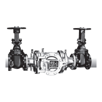
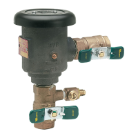
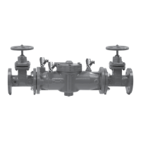
Series 919
Reduced Pressure Zone Assemblies
Sizes:
1
⁄4" – 2" (8 – 50mm)
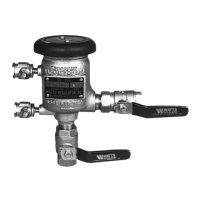
Watts 919QT
RP/IS-919
Limited Warranty: Watts Regulator Company warrants each product to be free from defects in material and workmanship under normal usage for a period of one year from the date of original ship-
ment. In the event of such defects within the warranty period, the Company will, at its option, replace or recondition the product without charge. This shall constitute the sole and exclusive remedy for
breach of warranty, and the Company shall not be responsible for any incidental, special or consequential damages, including without limitation, lost profits or the cost of repairing or replacing other
property which is damaged if this product does not work properly, other costs resulting from labor charges, delays, vandalism, negligence, fouling caused by foreign material, damage from adverse water
conditions, chemical, or any other circumstances over which the Company has no control. This warranty shall be invalidated by any abuse, misuse, misapplication or improper installation of the prod-
uct. THIS WARRANTY IS IN LIEU OF ALL OTHER WARRANTIES, EXPRESS OR IMPLIED, INCLUDING ANY IMPLIED WARRANTIES OF MERCHANTABILITY OR FITNESS FOR A PARTICULAR PURPOSE.
Any implied warranties that are imposed by law are limited in duration to one year.
Some States do not allow limitations on how long an implied warranty lasts, and some States do not allow the exclusion or limitation of incidental or consequential damages. Therefore the above limi-
tations may not apply to you. This Limited Warranty gives you specific legal rights, and you may have other rights that vary from State to State. You should consult applicable state laws to determine
your rights.
• Installation • Service
• Repair Kits • Maintenance
For field testing procedure, send for IS-TK-DL, IS-TK-9A,
IS-TK-99E and IS-TK-99D.
For other repair kits and service parts, send for PL-RP-BPD.
For technical assistance, contact your local Watts
representative on back page.
IMPORTANT: Inquire with governing authorities for local installa-
tion requirements.
NOTE: For Australia and New Zealand, line strainers should be
installed between the upstream shutoff valve and the inlet of the
backflow preventer.
Its important that this assembly be tested periodically in compli-
ance with local codes, but at least once per year or more as serv-
ice conditions warrant. If installed on a fire sprinkler system, all
mechanical checks, such as alarm checks and backflow preven-
ters, should be flow tested and inspected internally in accordance
with NFPA 13 and NFPA 25.