EasyManua.ls Logo

Watts 800 Series - User Manual

Watts 800 Series
2 pages
Print Icon
To Next Page IconTo Next Page
Loading...
INSTRUCTIONS FOR INSTALLING
Series 800
Anti-Siphon Pressure Type
Vacuum Breaker
Sizes:
1
2" through 2" (15-50mm)
When installed in accordance with these instructions
this valve is designed to prevent back-siphonage of
polluted water into a potable water supply. The No.
800 is ideally suited for industrial processing systems
and other continuous pressure applications. The valve
can be placed in the hot or cold supply lines connected
to a potable water supply system where water enters
the equipment below its overflow level.
Examples:
Where there is no danger of freezing and a drain or run-
off is available.
Cooling Tower and Process Water
Commercial Laundry Machines
Swimming Pools
Chemical Plating Tanks
Photo Tanks
Large Toilet and Urinal Facilities
Heat Exchangers
Degreasers
Live Stock Water Systems
PRESSURE - TEMPERATURE
Working Temp: 33°F - 210°F (56°C - 99°C)
Max. Pressure: 150 psi (10 bars)
Min. Pressure: 15 psi (1 bar)
Important Note: Vacuum breakers are not designed,
tested or approved to protect against backpressure
backflow or water hammer shock. For protection
against backpressure backflow, install a Watts Model
909 Reduced Pressure Backflow Preventer. For pro-
tection against water hammer shock install Watts Model
15 Shock Arrestors.
Important Start-Up
ASSE standard 1020 requires that the atmo-
spheric vent valve remains open until the valve
body pressure exceeds 1 psi. Until this pres-
sure is reached, some amount of spillage will
occure at the atmospheric vent. In order to
minimize this leakage on start-up, close the
downstream shut-off valve and open inlet
shut-off valve quickly.
Operation
When the down stream pressure drops to 1 psi or below,
the spring loaded disc float opens the atmospheric vent
and the spring loaded check valve closes the inlet. This
prevents the creation of a vacuum in the discharge line
and prevents back siphonage. As water flows through the
valve, it pushes the check valve open and lifts the disc
float which closes the atmospheric vent, thus preventing
leakage. The disc float is free floating without close fitting
guides which assures freedom from sticking. The durable
silicone disc on the disc float and check valve permits use
on hot and cold water lines.
3
4" - 2" IAPMO Listed
Watts
No. 800
Watts No. 909
Reduced Pressure
Backflow Preventer
Meter
Potable Line
Non Potable Line
Wash
Sink
Drinking Domestic
Fountain Water Heater
Potable Supply - Flow
Tank Vat
Degreaser
*12" Minimum (305mm)
IS-800
Isolation Potable Water System From Non-Potable Line
Question and Answer IconNeed help?

Do you have a question about the Watts 800 Series and is the answer not in the manual?

Summary

Pressure and Temperature

Important Start-Up Procedures

Valve Operation

Installation Guidelines

Service and Replacement Parts

Disassembly Instructions

Steps for safely taking apart the vacuum breaker for inspection or repair.

Reassembly Process

Guidance on putting the vacuum breaker back together using new parts.

Series 800 Repair Kits

Information on available repair kits for different sizes of Series 800 breakers.

Overview

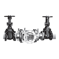
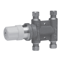
The Watts Series 800 Anti-Siphon Pressure Type Vacuum Breaker is a device designed to prevent back-siphonage of polluted water into a potable water supply system. It is suitable for industrial processing systems and other continuous pressure applications, particularly where water enters equipment below its overflow level, and can be placed in both hot and cold supply lines. The device is available in sizes from 1/2" through 2" (15-50mm) and is ASSE, UPC, and IAPMO listed (for 3/4" - 2").

Function Description:

The primary function of the Series 800 vacuum breaker is to protect potable water systems from contamination due to back-siphonage. When the downstream pressure drops to 1 psi or below, the spring-loaded disc float opens the atmospheric vent, and the spring-loaded check valve closes the inlet. This action prevents the creation of a vacuum in the discharge line, thereby preventing back-siphonage. As water flows through the valve, it pushes the check valve open and lifts the disc float, which then closes the atmospheric vent, preventing leakage. The disc float is designed to be free-floating without close-fitting guides, ensuring freedom from sticking. The durable silicone disc on both the disc float and check valve allows for use with both hot and cold water lines.

Important Technical Specifications:

  • Sizes: 1/2" through 2" (15-50mm)
  • Working Temperature: 33°F - 210°F (56°C - 99°C)
  • Maximum Pressure: 150 psi (10 bars)
  • Minimum Pressure: 15 psi (1 bar)
  • Listings: ASSE, UPC, 3/4" - 2" IAPMO Listed

Usage Features:

The Series 800 is recommended for applications where there is no danger of freezing and a drain or run-off is available. Examples of suitable applications include:

  • Cooling Tower and Process Water
  • Commercial Laundry Machines
  • Swimming Pools
  • Chemical Plating Tanks
  • Photo Tanks
  • Large Toilet and Urinal Facilities
  • Heat Exchangers
  • Degreasers
  • Live Stock Water Systems

Installation Requirements:

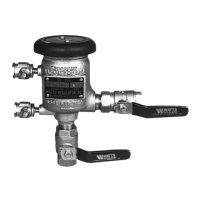
According to plumbing codes, the valve must be installed at least 12" (305mm) above the overflow level or flood rim of the fixture or container being supplied. It must be installed with the supply line connected to the bottom or inlet of the valve and in a vertical position, allowing for periodic inspection, servicing, and testing. Due to possible water spillage during operation, the valve should not be installed in concealed locations, inside a wall, or where freezing or spillage could cause water damage if a drain is not available.

Important Start-Up Procedure:

ASSE standard 1020 requires that the atmospheric vent valve remains open until the valve body pressure exceeds 1 psi. During start-up, some spillage will occur at the atmospheric vent until this pressure is reached. To minimize this leakage, it is recommended to close the downstream shut-off valve and open the inlet shut-off valve quickly.

Limitations:

Vacuum breakers are not designed, tested, or approved to protect against backpressure backflow or water hammer shock. For protection against backpressure backflow, a Watts Model 909 Reduced Pressure Backflow Preventer should be installed. For protection against water hammer shock, Watts Model 15 Shock Arrestors should be installed.

Maintenance Features:

The internal parts of the Series 800 can be removed, repaired, or inspected without removing the valve from the piping. This facilitates easier maintenance and repair.

Disassembly Procedure:

  1. Shut off the supply pressure and drain the valve.
  2. Remove the two hood screws and the hood.
  3. Place a wrench on the parallel flats of the bonnet and stem assembly. Turn counter-clockwise and remove.
  4. Remove the vent disc holder assembly.
  5. Press down on the spring retainer and disengage it from the retaining lugs. Then turn 90° and remove.
  6. Remove the spring retainer and spring. Note that the large diameter of the spring is down on the guide assembly.
  7. Remove the check disc holder and guide assembly.
  8. Disassemble the check disc holder assembly.

Reassembly Procedure:

Reassemble the valve in the reverse order of disassembly, utilizing new parts from the repair kit as needed.

Available Repair Kits:

  • Check Kits (RK800 CK): Include check disc assembly (disc and disc holder), Bonnet O-ring, and spring. Available for 1/2" - 1" (Order No. 0886027) and 11/4" - 2" (Order No. 0886028).
  • Vent Float Kits (RK800 V): Include float vent disc assembly (vent float, seal, and spring) and Bonnet O-ring. Available for 1/2" - 1" (Order No. 0886025) and 11/4" - 2" (Order No. 0886026).
  • Bonnet Kits (RK800 B): Include Bonnet, Guide stem, Washer, Spring, and Bonnet O-ring. Available for 1/2" - 1" (Order No. 0886023) and 11/4" - 2" (Order No. 0886024).
  • Rubber Parts Kits (RK800 RT): Include Vent disc, Check disc, and Bonnet O-ring. Available for 1/2" - 1" (Order No. 0886021) and 11/4" - 2" (Order No. 0886022).

Maintenance Recommendation:

Annual inspection of all water system safety and control valves is required and necessary. Regular inspection, testing, and cleaning ensure maximum life and proper function of the device.

California Proposition 65 Warning:

This product contains chemicals known to the State of California to cause cancer and birth defects or other reproductive harm. Installers are required by California law to provide this warning to the consumer.

Watts 800 Series Specifications

General IconGeneral
BrandWatts
Model800 Series
CategoryControl Unit
LanguageEnglish

Related product manuals